Dump Truck – Construction Equipment
Dump trucks or production trucks are those that are used for transporting loose material such as sand, dirt, and gravel for construction. The typical dump truck is equipped with a hydraulically operated open box bed hinged at the rear, with the front being able to be lifted up to allow the contents to fall out on the ground at the site of delivery.Dump trucks come in many different configurations with each one specified to accomplish a specific task in the construction chain.
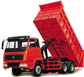
The standard dump truck is a full truck chassis with the dump body mounted onto the frame. The dump body is raised by a hydraulic ram lift that is mounted forward of the front bulkhead, normally between the truck cab and the dump body. The standard dump truck also has one front axle, and one or more rear axles which normally has dual wheels on each side. The common configurations for standard dump trucks include the six wheeler and ten wheeler.
Transfer dump truck
For the amount of noise made when transferring, the transfer dump truck is easy to recognize. It’s a standard dump truck that pulls a separate trailer which can be loaded with sand, asphalt, gravel, dirt, etc. The B box or aggregate container on the trailer is
powered by an electric motor and rides on wheels and rolls off of the trailer and into the main dump box. The biggest advantage with this configuration is to maximize payload capacity without having to sacrifice the maneuverability of the short and nimble dump truck standards.
Semi trailer end dump truck
The semi end dump truck is a tractor trailer combination where the trailer itself contains the hydraulic hoist. The average semi end dump truck has a 3 axle tractor that pulls a 2 axle semi trailer. The advantage to having a semi end dump truck is rapid unloading.
The semi end dump truck is a tractor trailer combination where the trailer itself contains the hydraulic hoist. The average semi end dump truck has a 3 axle tractor that pulls a 2 axle semi trailer. The advantage to having a semi end dump truck is rapid unloading.
Semi trailer bottom dump truck
A bottom dump truck is a 3 axle tractor that pulls a 2 axle trailer with a clam shell type dump gate in the belly of the trailer. The biggest advantage of a semi bottom dump truck is the ability to lay material in a wind row. This type of truck is also maneuverable in reverse as well, unlike the double and triple trailer configurations.
A bottom dump truck is a 3 axle tractor that pulls a 2 axle trailer with a clam shell type dump gate in the belly of the trailer. The biggest advantage of a semi bottom dump truck is the ability to lay material in a wind row. This type of truck is also maneuverable in reverse as well, unlike the double and triple trailer configurations.
Double and triple trailer
The double and triple bottom dump trucks consist of a 2 axle tractor pulling a semi axle semi trailer and an additional trailer. These types of dump trucks allow the driver to lay material in wind rows without having to leave the cab or stop the truck. The biggest disadvantage is the difficulty in going in reverse.
The double and triple bottom dump trucks consist of a 2 axle tractor pulling a semi axle semi trailer and an additional trailer. These types of dump trucks allow the driver to lay material in wind rows without having to leave the cab or stop the truck. The biggest disadvantage is the difficulty in going in reverse.
Side dump trucks
Side dump trucks consist of a 3 axle trailer pulling a 2 axle semi trailer. It offers hydraulic rams that tilt the dump body onto the side, which spills the material to the left or right side of the trailer. The biggest advantages with these types of dump trucks are that they allow rapid unloading and carry more weight than other dump trucks.
Side dump trucks consist of a 3 axle trailer pulling a 2 axle semi trailer. It offers hydraulic rams that tilt the dump body onto the side, which spills the material to the left or right side of the trailer. The biggest advantages with these types of dump trucks are that they allow rapid unloading and carry more weight than other dump trucks.
In addition to this, side dump trucks are almost impossible to tip over while dumping, unlike the semi end dump trucks which are very prone to being upset or tipped over. The length of these trucks impede maneuverability and limit versatility.
Off road dump trucks
Off road trucks resemble heavy construction equipment more than they do highway dump trucks. They are used strictly for off road mining and heavy dirt hauling jobs, such as excavation work. They are very big in size, and perfect for those time when you need to dig out roads and need something to haul the massive amounts of dirt to another location.
Off road trucks resemble heavy construction equipment more than they do highway dump trucks. They are used strictly for off road mining and heavy dirt hauling jobs, such as excavation work. They are very big in size, and perfect for those time when you need to dig out roads and need something to haul the massive amounts of dirt to another location.
This article was submitted by Er. Ankush
Front Loader – Construction Equipment
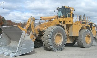
Also known as a front end loader, bucket loader, scoop loader, or shovel, the front loader is a type of tractor that is normally wheeled and uses a wide square tilting bucket on the end of movable arms to lift and move material around.The loader assembly may be a removable attachment or permanently mounted on the vehicle. Often times, the bucket can be replaced with other devices or tools, such as forks or a hydraulically operated bucket.
Larger style front loaders, such as the Caterpillar 950G or the Volvo L120E, normally have only a front bucket and are known as front loaders, where the small front loaders are often times equipped with a small backhoe as well and called backhoe loaders or loader backhoes.Loaders are primarily used for loading materials into trucks, laying pipe, clearing rubble, and also digging. Loaders aren’t the most efficient machines for digging, as they can’t dig very deep below the level of their wheels, like the backhoe can.
The deep bucket on the front loader can normally store around 3 – 6 cubic meters of dirt, as the bucket capacity of the loader is much bigger than the bucket capacity of a backhoe loader. Loaders aren’t classified as excavating machinery, as their primary purpose is other than moving dirt.In construction areas, mainly when fixing roads in the middle of the city, front loaders are used to transport building materials such as pipe, bricks, metal bars, and digging tools. Front loaders are also very useful for snow removal as well, as you can use their bucket or as a snow plow. They can clear snow from the streets and highways, even parking lots.They will sometimes load the snow into dump trucks which will then haul it away.
Unlike the bulldozer, most loaders are wheeled and not tracked. The wheels will provide better mobility and speed and won’t damage paved roads near as much as tracks, although this will come at the cost of reduced traction. Unlike backhoes or tractors fitted with a steel bucket, large loaders don’t use automotive steering mechanisms, as they instead steer by a hydraulically actuated pivot point set exactly between the front and rear axles.This is known as articulated steering and will allow the front axle to be solid, therefore allowing it to carry a heavier weight.
Articulated steering will also give a reduced turn in radius for a given wheelbase. With the
front wheels and attachment rotating on the same axis, the operator is able to steer his load in an arc after positioning the machine, which can come in quite handy. The problem is that when the machine is twisted to one side and a heavy load is lifted high in the air, it has a bigger risk of turning over.
front wheels and attachment rotating on the same axis, the operator is able to steer his load in an arc after positioning the machine, which can come in quite handy. The problem is that when the machine is twisted to one side and a heavy load is lifted high in the air, it has a bigger risk of turning over.
This article was submitted by Er. Ankush
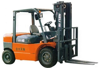
Forklift
Sometimes called a forklift truck, the forklift is a powerful industrial truck that is used to lift and transport material by steel forks that are inserted under the load. Forklifts are commonly used to move loads and equipment that is stored on pallets. The forklift was developed in 1920, and has since become a valuable piece of equipment in many manufacturing and warehousing operations.
Types of Forklifts
The most common type of design with forklifts is the counter balance. Other types of designs include the reach truck and side loader, both of which are used in environments where the space is at a minimum.
The most common type of design with forklifts is the counter balance. Other types of designs include the reach truck and side loader, both of which are used in environments where the space is at a minimum.
Control and capability
Forklifts are available in many types and different load capacities. In the average warehouse setting,most forklifts have load capacities of around five tons. Along with the control to raise and lower the forks, you can also tilt the mast to compensate for the tendency of the load to angle the blades towards the ground and risk slipping it off the forks. The tilt will also provide a limited ability to operate on ground that isn’t level.There are some variations that allow you to move the forks and backrest laterally, which allows easier placement of a load. In addition to this, there are some machines that offer hydraulic control to move the forks together or further apart, which removes the need for you to get out of the cab to manually adjust for a different size load.
Another forklift variation that is sometimes used in manufacturing facilities, will utilize forklifts with a clamp attachment that you can open and close around a load, instead of having to use forks. Products such as boxes, cartons, etc., can be moved with the clamp attachment.Go to www.warmmilkybiscuit.com
Safety
Forklifts are rated for loads at a specified maximum weight and a specified forward type center of gravity. All of this information is located on a nameplate that is provided by the manufacturer and the loads cannot exceed these specifications. One of the most important aspects of operating a forklift is the rear wheel steering. Even though this helps to increase maneuverability in tight cornering situations, it differs from the traditional experience of a driver with other wheeled vehicles as there is no caster action. Another critical aspect of the forklift is the instability. Both the forklift and the load must be considered a unit, with a varying center of gravity with every movement of the load.You must never negotiate a turn with a forklift at full speed with a raised load, as this can easily tip the forklift over.
Forklifts are rated for loads at a specified maximum weight and a specified forward type center of gravity. All of this information is located on a nameplate that is provided by the manufacturer and the loads cannot exceed these specifications. One of the most important aspects of operating a forklift is the rear wheel steering. Even though this helps to increase maneuverability in tight cornering situations, it differs from the traditional experience of a driver with other wheeled vehicles as there is no caster action. Another critical aspect of the forklift is the instability. Both the forklift and the load must be considered a unit, with a varying center of gravity with every movement of the load.You must never negotiate a turn with a forklift at full speed with a raised load, as this can easily tip the forklift over.
This article was submitted by – Er. Ankush
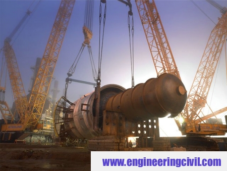
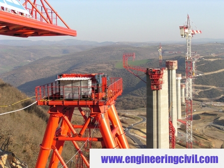
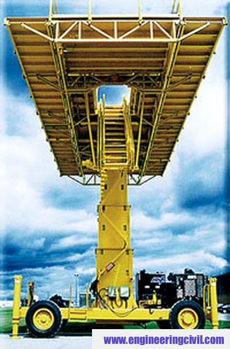
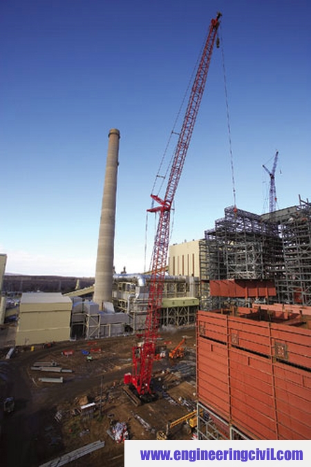
Various Types Of Cranes
A crane is a tower or derrick that is equipped with cables and pulleys that are used to lift and lower material. They are commonly used in the construction industry and in the manufacturing of heavy equipment. Cranes for construction are normally temporary
structures, either fixed to the ground or mounted on a purpose built vehicle.
structures, either fixed to the ground or mounted on a purpose built vehicle.
They can either be controlled from an operator in a cab that travels along with the crane, by a push button pendant control station, or by radio type controls. The crane operator is ultimately responsible for the safety of the crews and the crane.
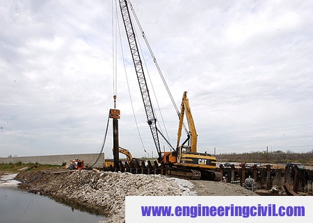
Mobile Cranes
The most basic type of crane consists of a steel truss or telescopic boom mounted on a mobile platform, which could be a rail, wheeled, or even on a cat truck. The boom is hinged at the bottom and can be either raised or lowered by cables or hydraulic cylinders.
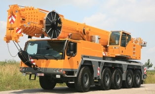
Telescopic Crane
This type of crane offers a boom that consists of a number of tubes fitted one inside of the other. A hydraulic mechanism extends or retracts the tubes to increase or decrease the length of the boom.
This type of crane offers a boom that consists of a number of tubes fitted one inside of the other. A hydraulic mechanism extends or retracts the tubes to increase or decrease the length of the boom.
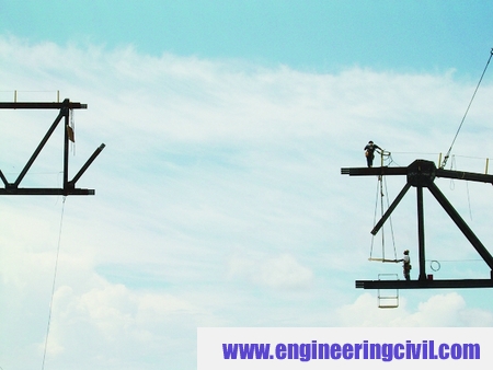
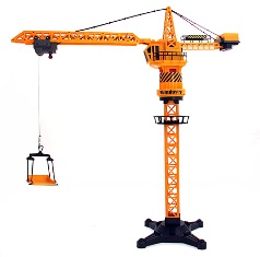
Tower Crane
The tower crane is a modern form of a balance crane. When fixed to the ground, tower cranes will often give the best combination of height and lifting capacity and are also used when constructing tall buildings.
The tower crane is a modern form of a balance crane. When fixed to the ground, tower cranes will often give the best combination of height and lifting capacity and are also used when constructing tall buildings.
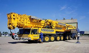
Truck Mounted Crane
Cranes mounted on a rubber tire truck will provide great mobility. Outriggers that extend vertically or horizontally are used to level and stabilize the crane during hoisting.
Cranes mounted on a rubber tire truck will provide great mobility. Outriggers that extend vertically or horizontally are used to level and stabilize the crane during hoisting.
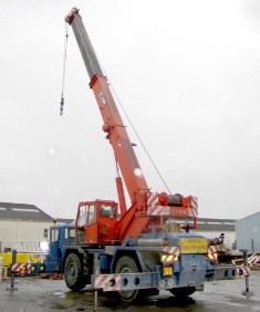
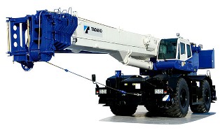
Rough Terrain Crane
A crane that is mounted on an undercarriage with four rubber tires, designed for operations off road. The outriggers extend vertically and horizontally to level and stabilize the crane when hoisting. These types of cranes are single engine machines where the same engine is used for powering the undercarriage as it is for powering the crane. In these types of cranes, the engine is normally mounted in the undercarriage rather than
in the upper portion.
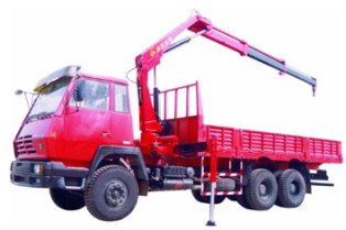
Loader Crane
A loader crane is a hydraulically powered articulated arm fitted to a trailer, used to load equipment onto a trailer. The numerous sections can be folded into a small space when the crane isn’t in use.
A loader crane is a hydraulically powered articulated arm fitted to a trailer, used to load equipment onto a trailer. The numerous sections can be folded into a small space when the crane isn’t in use.
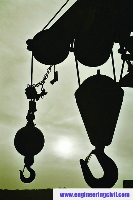
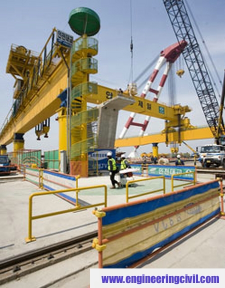
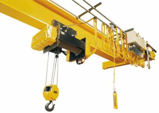
Overhead Crane
Also refered to as a suspended crane, this type is normally used in a factory, with some of them being able to lift very heavy loads. The hoist is set on a trolley which will move in one direction along one or two beams, which move at angles to that direction along elevated or ground level tracks, often mounted along the side of an assembly area.
Also refered to as a suspended crane, this type is normally used in a factory, with some of them being able to lift very heavy loads. The hoist is set on a trolley which will move in one direction along one or two beams, which move at angles to that direction along elevated or ground level tracks, often mounted along the side of an assembly area.
In the excavation world, cranes are used to move equipment or machinery. Cranes can quickly and easily move machinery into trenches or down steep hills, or even pipe. There are many types of cranes available, serving everything from excavation to road work.
Cranes are also beneficial to building bridges or construction. For many years, cranes have proven to be an asset to the industry of construction and excavating. Crane operators make really good money, no matter what type of crane they are operating.
This article was submitted by Er. Vikrant
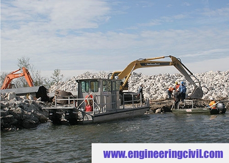
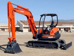
Compact Excavator
The compact hydraulic excavator can be a tracked or wheeled vehicle with an approximate operating weight of 13,300 pounds.Normally, it includes a standard backfill blade and features an independent boom swing. The compact hydraulic excavator is also known as a mini excavator.
A compact hydraulic excavator is different from other types of heavy machinery in the sense that all movement and functions of the machine are accomplished through the transfer of hydraulic fluid.The work group and blade are activated by hydraulic fluid acting upon hydraulic cylinders.The rotation and travel functions are also activated by hydraulic fluid powering hydraulic motors.
Most types of compact hydraulic excavators have three assemblies – house, undercarriage, and the work group.
House
The house structure contains the compartment for the operator, engine compartment, hydraulic pump and also the distribution components. The house structure is attached to the top of the undercarriage via swing bearing. Along with the work group, them house is able to rotate upon the undercarriage without limit due to a hydraulic distribution valve that supplies oil to the undercarriage components.
The house structure contains the compartment for the operator, engine compartment, hydraulic pump and also the distribution components. The house structure is attached to the top of the undercarriage via swing bearing. Along with the work group, them house is able to rotate upon the undercarriage without limit due to a hydraulic distribution valve that supplies oil to the undercarriage components.
Undercarriage
The undercarriage of compact excavators consists of rubber or steel tracks, drive sprockets, rollers,idlers, and associated components and structures.The undercarriage is also home to the house structure and the work group.
The undercarriage of compact excavators consists of rubber or steel tracks, drive sprockets, rollers,idlers, and associated components and structures.The undercarriage is also home to the house structure and the work group.
Work group
The work group consists of the boom, dipper or arm, and attachment. It is connected to the front of the house structure via a swinging frame that allows the work group to be hydraulically pivoted left or right in order to achieve offset digging for trenching parallel with the tracks.
The work group consists of the boom, dipper or arm, and attachment. It is connected to the front of the house structure via a swinging frame that allows the work group to be hydraulically pivoted left or right in order to achieve offset digging for trenching parallel with the tracks.
Independent boom swing
The purpose of the boom swing is for offset digging around obstacles or along foundations,
walls, and forms. Another use is for cycling in areas that are too narrow for cab rotation. Another major advantage of the compact excavator is the independent boom swing.
The purpose of the boom swing is for offset digging around obstacles or along foundations,
walls, and forms. Another use is for cycling in areas that are too narrow for cab rotation. Another major advantage of the compact excavator is the independent boom swing.
Backfill blade
The backfill blade on compact excavators are used for grading, leveling, backfilling, trenching, and general dozer work. The blade can also be used to increase the dumping height and digging depth depending on it’s position in relation to the workgroup.
The backfill blade on compact excavators are used for grading, leveling, backfilling, trenching, and general dozer work. The blade can also be used to increase the dumping height and digging depth depending on it’s position in relation to the workgroup.
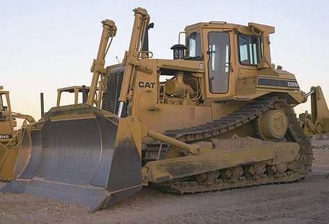
Bulldozer – Construction Equipment
The bulldozer is a very powerful crawler that is equipped with a blade. The term bulldozer is often used to mean any type of heavy machinery, although the term actually refers to a tractor that is fitted with a dozer blade. Often times, bulldozers are large and extremely powerful tracked vehicles. The tracks give them amazing ground mobility and hold through very rough terrain. Wide tracks on the other hand, help to distribute the weight of the dozer over large areas, therefore preventing it from sinking into sandy or muddy ground.
Bulldozers have great ground hold and a torque divider that’s designed to convert the power of the engine into dragging ability, which allows it to use its own weight to push heavy objects and even remove things from the ground. Take the Caterpillar D9 for example, it can easily tow tanks that weight more than 70 tons. Due to these attributes,bulldozers are used to clear obstacles, shrubbery and remains of structures and buildings.
The blade on a bulldozer is the heavy piece of metal plate that is installed on the front. The
blade pushes things around. Normally, the blade comes in 3 varieties:
1. A straight blade that is short and has no lateral curve, no side wings, and can be used
only for fine grading.
2. A universal blade, or U blade, which is tall and very curved, and features large side wings to carry more material around.
3. A combination blade that is shorter,offers less curvature, and smaller side wings.
Modifications
Over time, bulldozers have been modified to evolve into new machines that are capable of things the original bulldozers weren’t. A good example is that loader tractors were created by removing the blade and substituting a large volume bucket and hydraulic arms which will raise and lower the bucket, therefore making it useful for scooping up the earth and loading it into trucks.Other modifications to the original bulldozer include making it smaller to where it can operate in small working areas where movement is very limited, such as mining caves and tunnels. Very small bulldozers are known as calfdozers.
History
The first types of bulldozers were adapted from farm tractors that were used to plough fields. In order to dig canals, raise earth dams, and partake in earthmoving jobs, the tractors were equipped with a thick metal plate in the front. Later on, this thick metal plate earned the name blade.
The blade of the bulldozer peels layers of soil and pushes it forward as the tractor advances.The blade is the heart and soul of the bulldozer, as it was the first accessory to make full use for excavation type jobs. As the years went by, when engineers needed equipment to complete larger jobs, companies such as CAT, Komatsu, John Deere, Case, and JCB started to manufacture large tracked earthmoving equipment.They were very loud, very large, and very powerful and therefore earned the nickname “bulldozer”.Over the years, the bulldozers got bigger, more powerful, and even more sophisticated. The important improvements include better engines,more reliable drive trains, better tracks, and even hydraulic arms that will enable more precise manipulation of the blade and automated controls.As an added option, bulldozers can come equipped with a rear ripping claw to break up pavement or loosen rocky soil.The best known manufacturer of bulldozer is CAT,which has earned a vast reputation for making
tough and durable, yet reliable machines.Even though the bulldozer started off a modified farmtractor, it rapidly became one of the most useful pieces of equipment with excavating and construction.
tough and durable, yet reliable machines.Even though the bulldozer started off a modified farmtractor, it rapidly became one of the most useful pieces of equipment with excavating and construction.
Submitted By : Er. Vikrant
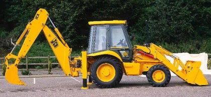
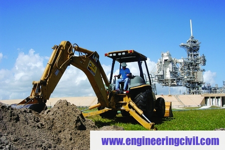
Backhoe Loader – Construction Equipment
Also referred to as a loader backhoe, the backhoe loader is an engineering and excavation vehicle that consists of a tractor, front shovel and bucket and a small backhoe in the rear end. Due to the small size and versatility, backhoe loaders are common with small construction projects and excavation type work.Originally invented in Burlington Iowa back in 1857, the backhoe loader is the most common variation of the classic farm tractor.As the name implies, it has a loader assembly on the front and a backhoe attachment on the back.
Anytime the loader and backhoe are attached it is never referred to as a tractor, as it is not normally used for towing and doesn’t normally have a PTO.When the backhoe is permanently attached, the machine will normally have a seat that can swivel to the rear to face the backhoe controls.Any type of removable backhoe attachments will normally have a seperate seat on the attachment itself.Backhoe loaders are common and can be used for many tasks, which include construction, light transportation of materials, powering building equipment, digging holes and excavating, breaking asphalt, and even paving roads.You can often replace the backhoe bucket with other tools such as a breaker for breaking and smashing concrete and rock. There are some loader buckets that offer a retractable bottom, which enable it to empty the load more quickly and efficiently.