What is the reason of adding steel wire mesh when using erosion control mat in slopes?
It is not uncommon that the use of erosion control mat in slopes is accompanied by the addition of steel wire mesh. The system of erosion control mesh with a steel wire mesh proves to be a more effective method to control surface erosion. In case surface erosion occurs even in the presence of erosion control mat, the soil debris could be trapped between the steel wire mesh and the slope surface. As such, the steel wire mesh essentially serves as an additional protective layer to avoid further occurrence of erosion.
This question is taken from book named – A Self Learning Manual – Mastering Different Fields of Civil Engineering Works (VC-Q-A-Method) by Vincent T. H. CHU.
This question is taken from book named – A Self Learning Manual – Mastering Different Fields of Civil Engineering Works (VC-Q-A-Method) by Vincent T. H. CHU.
What is the purpose of installation of erosion control mat in slopes?
Steep slopes are prone to intermittent high velocity flows during rainstorm and this causes erosion at slope surface which prevents the growth of vegetation.
Erosion control mat is installed to control soil erosion and provide soil stability until vegetation can be established. The principal function of erosion control mat is to prevent pre-vegetated soil loss by stabilizing and protecting soils from rainfall and surface erosion. Moreover, it could provide a long-term artificial erosion control system which would increase the shear resistance of vegetation and provide long-term, tenacious reinforcement of the root system.
This question is taken from book named – A Self Learning Manual – Mastering Different Fields of Civil Engineering Works (VC-Q-A-Method) by Vincent T. H. CHU.
What are the functions of drainage system and protective covers of slopes?
In Hong Kong the angle of fill slope is about 30o– 40o to the horizontal while the angle of cut slope is about 50o– 60oto the horizontal. To protect the slope from surface erosion and water infiltration, it is covered with impermeable hard cover like chunam and shotcrete. Chunam is a mixture of soil, cement and lime and is usually applied in two layers with the thickness of each layer of 25mm. For shotcrete, mesh reinforcement may be provided inside it to enhance tensile strength of cover, thereby reducing the risk of tensile cracking of slope cover.
Weepholes are normally provided in slopes to prevent building up of water pressure in the slope and subsequently this causes cracking and disintegration of slope cover. For gentle slope, hydroseeding may be used and geofabric may be introduced on slope surface to guard against possible surface erosion.
U-channels are provided on the crest and toe of slope to divert and collect the rain falling on slope surface. Catchpits are provided at the intersection or junctions of drains to avoid possible splashing of water.
This question is taken from book named – A Self Learning Manual – Mastering Different Fields of Civil Engineering Works (VC-Q-A-Method) by Vincent T. H. CHU.
What are the major causes of rockfall?
The causes of rockfall can be broadly classified into the following two reasons:
(i) Freezing and thawing and the subsequent development of vegetation root pressure in slopes is one of the major causes of rockfall in some countries like Europe. Moreover, rockfall can also be triggered by heavy rainstorms which bring about surface erosion and generate water pressure in rock joints.
(ii) Rockfall can also be induced by poor joint patterns and low strength and water pressure in joints.
This question is taken from book named – A Self Learning Manual – Mastering Different Fields of Civil Engineering Works (VC-Q-A-Method) by Vincent T. H. CHU.
Why do landslides occur though the rainfall has not led to full saturation in the sliding zone?
From soil mechanics, it tells us that unsaturated soils get its strength from three main components, namely, friction, cohesion and suction. In building a sand castle in a beach, experience tells us that when sand is too dry or too wet, the castle can hardly be built. However, when the sand is partially saturated, the suction (negative pore water pressure) holds the sand together and provides the strength the build the castle.
In the event of intensive rainfall, the soils cannot get away the water at the rate it is penetrating into the slope and this results in wetting up of the subsurface soils. When the slopes gets too wet (but not yet saturated), it loose much strength in terms of suction (negative pore water pressure) and results in slope failure. This occurs despite the fact that the sliding mass is well above the ground water table.
In Hong Kong about 80% of landslides occur owing to erosion and loss in suction. Only less than 20% of landslides occur as a result of increase of pore water pressure, leading to the decrease in shear strength.
How are landslides triggered by rainfall?
After rainfall, groundwater pressure is built up and this elevates the ground water table. The water inside the pores of soil reduces the effective stress of soils. Since shear strength of soils is represented by the following relations:
Shear strength = cohesion + effective stress x tan0 where 0 is the friction angle of soils
Hence, the presence of water causes a reduction of shear strength of soils and this may lead to landslide. On the other hand, the rainfall creates immediate instability by causing erosion of slop surface and results in shallow slope failure by infiltration. In addition, the rain may penetrate slope surface openings and forms flow paths. As a result, this may weaken the ground.
This question is taken from book named – A Self Learning Manual – Mastering Different Fields of Civil Engineering Works (VC-Q-A-Method) by Vincent T. H. CHU.
Does cutting slope cause slope deformation or slope failure?
Slope cutting causes stress relief in slopes which may cause slope movement. For instance, for weathered rocks the horizontal stresses would be relatively low when compared with normally consolidated soils.
Consequently, a major cut on the slope formed by weather rock may result in the development of tensile stresses in the slope, leading to slope movement.
This question is taken from book named – A Self Learning Manual – Mastering Different Fields of Civil Engineering Works (VC-Q-A-Method) by Vincent T. H. CHU.
Why are filled slopes vulnerable to slope failure?
Filled slopes constructed in many decades ago are mostly sub-standard. The relative density of filled slopes may be below 85% and is readily subjected to liquefaction. To rectify the situation, the sloped are reconstructed by excavation of 3m measured vertically from slope surface. Then, compaction should be carried out in thin layers to achieve in-situ density of not less than 95% of maximum dry density. After compaction, the compacted layer would not vulnerable to liquefaction failure. Moreover, it is less permeable than loose fill upon compaction and prevents water entry into underlying soils inside the slope.
For the case of Hong Kong, most fill slopes constructed before 1977 were formed by end-tipping so that they are in a loose state and poses hazard to developments nearby.
This question is taken from book named – A Self Learning Manual – Mastering Different Fields of Civil Engineering Works (VC-Q-A-Method) by Vincent T. H. CHU.
What is the difference in failure slip surface between slopes with cohesive and granular materials?
When cohesive strength is zero (i.e. slopes of granular types), the slip surface is of shallow failure type and is parallel to the slope surface.
When friction angle is zero (i.e. slopes of clayey types), the slip surface is if deep seated failure. The factor of safety of slopes is nearly independent of the angle of slopes because the weight of deep seated failure regime is much greater than the slope.
Normally, non-circular failure surface is always more critical than circular one for two dimensional analysis.
This question is taken from book named – A Self Learning Manual – Mastering Different Fields of Civil Engineering Works (VC-Q-A-Method) by Vincent T. H. CHU.
Other than liquefaction, what are the possible causes of failure of loose fill slopes?
Other than static liquefaction, slow-moving slips driven by transient pore water pressure leading to high speed landslide are the other possible cause of failure of loose fill slopes.
For loose fill lying on low permeability soil layers, there is potential storage of infiltrating water when the slope of underlying low-permeability soil layer is mild. As such, there is a localized zone of high transient pore water pressure induced within the fill material. Flowslides normally start with a local slip caused by transient pore water pressure by soil layering or flow restriction. Then, the nature of slow-moving soil debris and the geometry of slip result in a fast landslide.
For loose fill lying on low permeability soil layers, there is potential storage of infiltrating water when the slope of underlying low-permeability soil layer is mild. As such, there is a localized zone of high transient pore water pressure induced within the fill material. Flowslides normally start with a local slip caused by transient pore water pressure by soil layering or flow restriction. Then, the nature of slow-moving soil debris and the geometry of slip result in a fast landslide.
Why are fill slopes compacted to dense state instead of loose state?
In rainstorm, the runoff from rainfall infiltrate into the top layer of fill slopes. It may result in saturation of this layer of fills leading to the decrease in soil suction. Consequently shallow slope failure may occur.
If the fill slope is in a loose state, the soils would tend to decrease in volume during deformation. As a result this induces a rise in pore-water pressure which triggers slope failure in form of mud-avalanche.
If the fill slope is in a dense state, the soils would tend in increase in volume during deformation and it only fails like a mud slump.
This question is taken from book named – A Self Learning Manual – Mastering Different Fields of Civil Engineering Works (VC-Q-A-Method) by Vincent T. H. CHU.
Is force and moment equilibrium satisfied by Janbu’s method, Bishop’s method and Morgenstern-Price method?
Janbu’s method and Morgenstern-Price method are non-circular analytical method and they are frequently used for soil slopes while Bishop’s method is circular analytical method. Bishop’s Simplified method and Janbu’s Simplified method assume that the inter-slice forces are horizontal and inter-slice shear forces are neglected.
This question is taken from book named – A Self Learning Manual – Mastering Different Fields of Civil Engineering Works (VC-Q-A-Method) by Vincent T. H. CHU.
| Equilibrium Method | Moment Equilibrium | Force Equilibrium | |
| Horizontal | Vertical | ||
| Janbu’s Simplified | No | Yes | Yes |
| Bishop’s Simplified | Yes | No | Yes |
| Morgenstern-Price | Yes | Yes | Yes |
How to Control Vibration In Blasting?
When ever explosive substances are used to blast, a large amount of vibration occurs. This vibration is not only dangerous for people working their but also to the neighboring structures. Therefore proper care must be taken to keep vibration in check.
The vibrations caused by blasting are related to velocity (V), wavelength (L) and frequency (f) as
L= V/f
Now Velocity V depends on the amplitude of the vibrations A and is given by
v=2pfA
Where p – pie = 3.14
Case – When we know velocity velocity v1 at a distance D1 from the explosion and wish to find velocity v2 at a distance D2 from the explosion
v2=(approx) v1(D1/D2)1.5
The scaled-distance formula is used for vibration control
V=H[D/(W)1/2]-b
Where
b and H are constants and depend on site.
Earth Quantities Hauled
Many people wonder that why the soil looks bulkier after excavation. The answer is that with increase in voids, the volume of soil increases and thus the soil pile looks bulkier. Here is a mathematical formula for this change in soil volume
Vb = VbL = (100/(100 + % swell))VL
where
Vb = original volume, yd3 (m3),
VL = loaded volume, yd3 (m3),
L = load factor
Similarly when we compact the soil, its volume decrease as voids are now filled.
Vc = VbS
where
Vc = compacted volume, yd3 (m3)
S = shrinkage factor.
Vb = VbL = (100/(100 + % swell))VL
where
Vb = original volume, yd3 (m3),
VL = loaded volume, yd3 (m3),
L = load factor
Similarly when we compact the soil, its volume decrease as voids are now filled.
Vc = VbS
where
Vc = compacted volume, yd3 (m3)
S = shrinkage factor.
What are the formulas For Earth Moving?
Whenever their is a movement, friction comes into action. The same is the case with earth moving equipments. We term this as rolling resistance and this has to be overcomed by vehicle engine so that it can move on that surface. This is the formula to calculate rolling resistance
R=RfW + RpPW
where
R = rolling resistance, lb (N)
p = tire penetration, in (mm)
Rf = rolling-resistance factor, lb/ton (N/tonne)
W = weight on wheels, ton (tonne)
Rp = tire-penetration factor, lb/ton in (N/tonne mm) penetration
Rf usually is taken as 40 lb/ton (or 2 percent lb/lb) (173 N/t) and Rp as 30 lb/ton in (1.5% lb/lb in) (3288 N/t mm).
So the above equation becomes
R=(2%+1.5 % p) W’=R’W’
where
W’ = weight on wheels, lb(N)
R’ = 2% + 1.5%p.
Case – When we have a slope
G = RgsW
where
G = grade resistance, lb(N)
Rg = grade-resistance factor = 20 lb/ton (86.3 N/t) = 1%
s = percent grade which is positive for uphill motion and negative for downhill motion.
The total road resistance is calculated by adding the rolling and grade resistances and is given by:
T = (R’+Rg s )W’ =(2%b + 1.5%p + 1%s)W’
Describe Compaction Equipment Rollers
Soil compaction is done by Rollers. Many models of these rollers can be found in the market. Depending on the soil type and conditions, we chose rollers to work on them. For example, for soils with high % of clay we mainly use Sheepsfoot rollers and for granular soils we use vibrating rollers. The selection of roller depends on other factors like speed, desired compaction etc
The table below shows the average speeds, mi/h (km/h) under normal conditions:
To calculate compaction production use the following formula
yd3/h (m3/h) = 16WSLFE/P
where
W = width of roller, ft (m)
P = number of passes
S = roller speed, mi/h (km / h)
L = lift thickness, in (mm)
F = ratio of pay yd3 ( m3) to loose yd3 ( m3)
The table below shows the average speeds, mi/h (km/h) under normal conditions:
| Type | mi/h | km/h |
| Grid rollers | 12 | 19.3 |
| Sheepsfoot rollers | 3 | 4.8 |
| Tamping rollers | 10 | 16.1 |
| Pneumatic rollers | 8 | 12.8 |
yd3/h (m3/h) = 16WSLFE/P
where
W = width of roller, ft (m)
P = number of passes
S = roller speed, mi/h (km / h)
L = lift thickness, in (mm)
F = ratio of pay yd3 ( m3) to loose yd3 ( m3)
Soil Compaction Tests
There are many types of Soil compaction tests which are performed on soil. Some of these are :-
1) The Sand Cone Method
One of the most common test to determine the field density of soil is the sand-cone method. But it has a major limitation that this test is not suitable for saturated and soft soils
The formula used are
Volume of soil, ft3 (m3)=[weight of sand filling hole, lb (kg)] /[ Density of sand, lb/ft3 (kg/m3)]
% Moisture = 100(weight of moist soil – weight of dry soil)/weight of dry soil
Field density, lb/ft3 (kg /m3)=weight of soil, lb (kg)/volume of soil, ft3 (m3)
Dry density=field density/(1 + % moisture/100)
% Compaction=100 (dry density)/max dry density
Maximum density is found by plotting a density–moisture curve.
2) California Bearing Ratio
The California bearing ratio (CBR) is used as a determine the quality of strength of a soil under a pavement. It also measures the thickness of the pavement, its base, and other layers.
CBR = F/Fo
where
F = force per unit area required to penetrate a soil mass with a 3-in2 (1935.6-mm2 ) circular piston (about 2 in (50.8 mm) in diameter) at the rate of 0.05 in/min (1.27 mm/min)
F0 = force per unit area required for corresponding penetration of a standard material.
3) Soil Permeability
Darcy’s law is applicable in determining the soil permeability. Darcy law states that
V = kiA
where
V = rate of flow, cm3 /s,
A = cross-sectional area of soil conveying flow, cm2
k = Coefficient of permeability which depends on grain-size distribution, void ratio and soil fabric. The value varies from 10 cm/s for gravel to less than 10–7 for clays.
What is the Settlement Under Foundations?
To calculate the approximate value of settlement the following equations is used. This establishes a relationship between loads on foundations and settlement
q/P = C1(1+2d/b) + C2/b
where
q = load intensity, lb/ft2 (kg/m2)
P= settlement, in (mm)
d =depth of foundation below ground surface, ft (m)
b=width of foundation, ft (m)
C1 =coefficient dependent on internal friction
C2 = coefficient dependent on cohesion
q/P = C1(1+2d/b) + C2/b
where
q = load intensity, lb/ft2 (kg/m2)
P= settlement, in (mm)
d =depth of foundation below ground surface, ft (m)
b=width of foundation, ft (m)
C1 =coefficient dependent on internal friction
C2 = coefficient dependent on cohesion
Bearing Capacity Of Soils
Ultimate bearing capacity is calculated by using Prandtl equation. When the footing is below the surface the ultimate bearing capacity of the soil is modified by (1 + Cd/b) where C = 2 for cohesionless soils and C= 0.3 for cohesive soils.
The Prandtl’s equation is :-
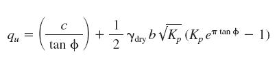
The Prandtl’s equation is :-
How to Determine the Stability Of Slopes?
To determine the stability of slopes, we first need to identify the type of soil. A cohesive soil behaves differently then Cohesionless Soils
Case 1 – When we have Cohesionless Soils
We consider the slope stable if it satisfies the following condition. Please note we consider no water seepage in this situation
i < f
where
i = slope of ground surface
f = angle of internal friction of soil
When seepage factor is introduced parallel to the slope and we assume that soil is totally saturated, the slope is considered stable if it fulfill this condition
tan i < (Yb/Ysat) tan f
Lateral Pressure From Surcharge
To counter any effect of a surcharge on retaining wall on a cohesionless soil or an unsaturated cohesive soil we need to apply a uniform horizontal load of magnitude KAp. This load is applied over the entire wall height.
In case of saturated cohesive soil, the entire surcharge value acts on the entire wall height. This is considered to be a uniform load acting horizontally.
In case of saturated cohesive soil, the entire surcharge value acts on the entire wall height. This is considered to be a uniform load acting horizontally.
What is the Water Pressure Retained by Retaining Walls?
We know that water exerts a pressure on the wall and this thrust is calculated by using the following formula
P = ½Yo H2
where H = height of water above bottom of wall, ft (m)
Yo= unit weight of water.
Unit of water is 62.4 lb/ft3 1001g/m for freshwater and 64 lb/ft3 or 1026.7 kg/m3 for saltwater.
The thrust applied by water is considered to be acting at a distance of H/3 from the bottom of the retaining wall. The pressure distribution is triangular and has the maximum pressure of 2P/H at the bottom of the wall.
What is Lateral Pressures In Cohesionless Soils?
The lateral pressure in cohesion less soils is given by following formula:-
Following terms are used in the formula given below
Y=unit weight of soil, lb/ft3 or kg/m3
P=total thrust of soil, lb/linear ft (kg/m) of wall
H= total height of wall, ft (m)
KA= coefficient of active pressure
Following terms are used in the formula given below
Y=unit weight of soil, lb/ft3 or kg/m3
P=total thrust of soil, lb/linear ft (kg/m) of wall
H= total height of wall, ft (m)
KA= coefficient of active pressure
What is the Lateral Pressure In Soils?
We know that The Rankine theory of lateral earth pressures is the most widely used theory to find the lateral pressure which is acting on retaining walls. But this theory has some assumptions which we need to know before hand.
Assumptions in the Rankine Theory of Lateral Earth Pressures
1) The pressure on the back of a vertical wall is the same as the pressure that would exist on a vertical plane in an infinite soil mass.
2) Their is no Friction between the wall and the soil.
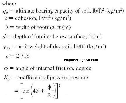
What is the Lateral Pressure of Cohesive Soils?
P=1/2YH2KA-2cH(KA)1/2
where
Y=unit weight of soil, lb/ft3 or kg/m3
P=total thrust of soil, lb / linear ft (kg/m) of wall
H= total height of wall, ft (m)
KA= coefficient of active pressure
c= cohesion, lb/ft2or kPa
Assumptions in the Rankine Theory of Lateral Earth Pressures
1) The pressure on the back of a vertical wall is the same as the pressure that would exist on a vertical plane in an infinite soil mass.
2) Their is no Friction between the wall and the soil.
What is the Lateral Pressure of Cohesive Soils?
P=1/2YH2KA-2cH(KA)1/2
where
Y=unit weight of soil, lb/ft3 or kg/m3
P=total thrust of soil, lb / linear ft (kg/m) of wall
H= total height of wall, ft (m)
KA= coefficient of active pressure
c= cohesion, lb/ft2or kPa
F
Physical Properties Of Soils
The soil properties and parameters can be broadly classified as
1)Physical
2)Engineering
3)Index
Physical soil properties include specific gravity, density, particle size and distribution and water content.
The water content represented by w of a soil sample is defined as the weight of free water in the sample expressed as a percentage of its dry weight.
The degree of saturation S is defined as the ratio of the volume of free water to its total volume of voids Vv
We need to calculate the value of e which is the void ratio to calculate degree of saturation. Once we know the value of e we can find S
S=wGs/e
where Gs – specific gravity of the soil particles and is usually in range of 2.67+ -0.05
The dry unit weight Yd(pronounced as gamma) of a soil specimen with any degree of saturation is calculated using the following formula
Yd=YwGsS/(1+wGs)
where w =unit weight of water having following values
Freshwater – 62.4 lb/ft3 or 1001 kg/m3
Seawater – 64.0 lb/ft31026.7 kg/m3
Fantastic insights on Uniaxial Geogrid applications! Your blog brilliantly highlights its role in stabilizing soil slopes. As a leading solution from top Uniaxial Geogrid Manufacturer, it provides superior tensile strength for slope reinforcement. Its durability ensures long-term soil stability. This blog is a must-read for geotechnical professionals! Looking forward to more informative posts!
ReplyDelete