In deep excavation, adjacent ground water table is drawn down which may affect the settlement of nearby buildings. What is the remedial proposal to rectify the situation?
One of the methods to control settlement of nearby buildings due to excavation work is by recharging. Water collected in wells in deep excavation is put back to the top of excavation in order to raise the drawn-down water table. The location of recharge should be properly selected to ensure the soil is sufficiently permeable to transfer the pumped water back near the affected buildings.
This question is taken from book named – A Self Learning Manual – Mastering Different Fields of Civil Engineering Works (VC-Q-A-Method) by Vincent T. H. CHU.
This question is taken from book named – A Self Learning Manual – Mastering Different Fields of Civil Engineering Works (VC-Q-A-Method) by Vincent T. H. CHU.
What are the problems associated with prestressed concrete piles (Daido)?
The origin of Daido piles comes from Japan where these prestressed concrete piles are used as replacement plies. Holes are pre-formed in the ground and Daido piles are placed inside these pre-formed holes with subsequent grouting of void space between the piles and adjacent ground. However, in Hong Kong Daido piles are constructed by driving into ground by hammers instead of the originally designed replacement method. Since the installation method of Daido piles is changed, construction problems like deformation of pile tip shoes, crushing of concrete at pile tip etc. occur. Reference is made to B. W. Choy (1993).
This question is taken from book named – A Self Learning Manual – Mastering Different Fields of Civil Engineering Works (VC-Q-A-Method) by Vincent T. H. CHU.
This question is taken from book named – A Self Learning Manual – Mastering Different Fields of Civil Engineering Works (VC-Q-A-Method) by Vincent T. H. CHU.
Should compaction be carried out to freshly-placed concrete piles?
In normal practice, reliance is placed on the self-compaction of specially designed concrete mixes to achieve adequate compaction. The use of vibrating devices like poker vibrators is seldom adopted for the compaction
of concrete piles. In fact, other than the consideration of the impracticality in using vibrating device in long piles, there is serious concern about the possible occurrence of aggregate interlock which poses difficulty during casing extraction. In the worst scenarios, the temporary casings together with reinforcement cages are extracted during the lifting up of pile casings. This is another reason which accounts for not using vibrating machines for piles with casing extraction.
This question is taken from book named – A Self Learning Manual – Mastering Different Fields of Civil Engineering Works (VC-Q-A-Method) by Vincent T. H. CHU.
Is the quality of concrete impaired by free-falling concrete placement method in bored piles?
Based on the research by STS Consultants Ltd., it was found that concrete placed by free falling below 120 feet would not suffer from the problem of segregation and the strength of concrete would not be detrimentally impaired provided that the piles’ bore and base are dry and free of debris. Moreover, it is presumed in the past that during free falling of fresh concrete into the pile bores the hitting of falling concrete in the reinforcement cage causes segregation. However, in accordance with the experimental results of STS Consultants Ltd., the striking of reinforcement cage by fresh concrete does not have significant effect on the strength of concrete
In addition, for long bored piles, it is impractical to conduct vibration to concrete. For concrete placed by free falling method, the impact action arising from free falling is assumed to induce adequate vibration. On the other hand, concrete placed by tremie method appears to be lack of vibration and this may affect the strength and integrity of concrete. The research results showed that the strength of vibrated concrete was slightly higher than unvibrated concrete. Vibration proved to have added advantage to concrete strength but not essential to achieve the design pile strength.
This question is taken from book named – A Self Learning Manual – Mastering Different Fields of Civil Engineering Works (VC-Q-A-Method) by Vincent T. H. CHU.
Is pile tip cover necessary for rock-socketed H-piles?
In current practice concrete cover is usually provided at the pile tips of pre-bored H-piles socketed in rock. The purpose of such arrangement is to avoid the potential occurrence of corrosion to H-piles in case concrete cover is not designed at pile tips. However, recent field and laboratory observations had reservation of this viewpoint. In case H-piles are designed to be placed directly on top of rock surface, it provides the tip
resistance to limit the pile movement in the event of bond rupture between grout and H-piles. As such, some contractors may choose to tamp the H-piles by using drop hammers to ensure the H-piles are founded directly on top of rock surface. Practically speaking, it poses difficulties during the process of tamping because there is a chance of possible buckling of long H-piles when too much energy is provided to the piles.
resistance to limit the pile movement in the event of bond rupture between grout and H-piles. As such, some contractors may choose to tamp the H-piles by using drop hammers to ensure the H-piles are founded directly on top of rock surface. Practically speaking, it poses difficulties during the process of tamping because there is a chance of possible buckling of long H-piles when too much energy is provided to the piles.
Why is sleeving applied in piles constructed on slopes?
For high-rise buildings constructed on steep cut slopes, these buildings are usually supported by large diameter piles. Though the piles are founded at some depth below the slopes, lateral load arising from wind on buildings may induce loads on the slop and causes slope failures. For shallow depths of slope which is marginally stable, it is more vulnerable to slope failure.
Hence, an annulus of compressible material called sleeving is introduced in piles so as to reduce the transfer of lateral loads from buildings to slopes.
This question is taken from book named – A Self Learning Manual – Mastering Different Fields of Civil Engineering Works (VC-Q-A-Method) by Vincent T. H. CHU.
What is the purpose of shaft grouting of deep foundations?
In shaft grouting operation, tube-a-manchette pipes are fixed at regular spacing to the reinforcement cage. After concreting barrettes/bored piles, a small volume of water is injected under high pressure into these pipes to crack the concrete. The cracking process should be carried out within 24 hours after concreting. The purpose of cracking is to create a path for grout to go through. About a week after concreting of barrette, grouting is then carried out in these pipes to improve the friction between the foundation and the surrounding soils.
This question is taken from book named – A Self Learning Manual – Mastering Different Fields of Civil Engineering Works (VC-Q-A-Method) by Vincent T. H. CHU.
This question is taken from book named – A Self Learning Manual – Mastering Different Fields of Civil Engineering Works (VC-Q-A-Method) by Vincent T. H. CHU.
Can down the hole hammer function below water table?
Down the hole hammer has been used extensively to form pre-bored holes as rock sockets for mini piles and pre-bored H piles. The hammer functions by driving repeatedly a drill bit using compressed air on the rock. However, the use of down the hole hammer is normally limited to hole diameter of 600mm.
In using down the hole hammer, compressed air serves to drive the drill bit and to expel the cuttings which are blown out to the air at ground level. However, for driving the hammer about 30m below ground water level, the air pressure has difficulty in coping with great water pressure. Moreover, blowing of cuttings by compressed air also dewaters the nearby soils. As a result, settlement of nearby ground may occur which is undesirable.
This question is taken from book named – A Self Learning Manual – Mastering Different Fields of Civil Engineering Works (VC-Q-A-Method) by Vincent T. H. CHU.
Why can’t normal Reversed Circulation Drills function in shallow rock conditions?
Reversed Circulation Drill (RCD) is normally used for forming large diameter rock socket. The method involves the exertion of a download force of roller cutter bits on rock, together with the action of rotation and
grinding of bits on rock. The cuttings are then removed by reverse circulation. The water and cuttings are airlifted through a central drill pipe, which is also used for rotating the drill bits.
To facilitate the grinding action on the rock, about 15 tons of force is used for each cutter. With such a high bit force, the drill frame has to be stationed by attaching to pile casing of bored piles. Therefore, during the
drilling operation, the pile casing is prevented from lifting up by the weight of drill rig and pile casing and the frictional forces developed between the ground and pile casing. Hence, in shallow rock conditions with short length of pile casings, it may affect the stability of RCD drill rig.
This question is taken from book named – A Self Learning Manual – Mastering Different Fields of Civil Engineering Works (VC-Q-A-Method) by Vincent T. H. CHU.
Should bentonite be added to improve the stability of grout?
For unstable grout, particles will come out of the grout suspension leading to incomplete grouting and clogging of pipes. The stability of grout can be improved by adding additives such as bentonite. However, bentonite
should not be used with very fine cements because its grain size is bigger than that of fine cements. Tests conducted previously confirm that a grout with bentonite is less stable under pressure.
It is commonly accepted that a fissure may be penetrated by grout with the grain size about 3-5 times smaller than the aperture of fissure. Hence, OPC cement may penetrate fissures of aperture greater than 0.4mm while microfine cement and ultrafine cement may penetrate fissures of aperture greater than 0.1mm and 0.03mm respectively.
What are the reasons in observed settlements in rockfill foundation?
Compression of rockfill is normally caused by a reduction in dimension of fill and by rearrangement of particles into closer packing.
When the rockfill are saturated, the strength of rock would be reduced accordingly. In fact, wetting of rock surfaces does not reduce the coefficient of sliding friction between rockfills. Considerable settlement may result not from the lubricating effect of water but from a reduction of rock strength at its point of contact. The contact points would then be crushed under intergranular force and the contact area increases until contact pressure is less than the strength of rockfill.
Rockfill with sharp corners proved to be more liable to settlement than those of well-rounded.
To minimize settlement of rockfill, the intergranular force should be reduced and this is achieved by grading the size of rock particles such that there is minimum amount of voids and hence a maximum amount of particle contacts. To avoid particle rearrangement under future loading, the rockfill should be properly compacted with earth-moving machinery.
This question is taken from book named – A Self Learning Manual – Mastering Different Fields of Civil Engineering Works (VC-Q-A-Method) by Vincent T. H. CHU.
In seismic liquefaction, what is the difference of pile failures mechanism between lateral spreading and buckling?
Most of design codes assume that pile fails during strong earthquake by lateral spreading. Lateral spreading is based on bending mechanism where the inertia and slope movement causes bending in piles. In essence, piles are considered as beams which are subjected to lateral loads such as slope movement leading to pile failure.
Piles are slender columns with lateral support from foundation soils. When the length of pile increases, the buckling loads decrease with the square of pile length. For buckling failure, soils around the piles lose the confining stress during earthquake and can hardly provide lateral support to piles. As such, the pile serves as an unsupported column with axial instability. It will buckle sideways in the direction of least bending stiffness under axial load.
This question is taken from book named – A Self Learning Manual – Mastering Different Fields of Civil Engineering Works (VC-Q-A-Method) by Vincent T. H. CHU.
When are prestressed tiebacks used in sheet piling works?
The use of prestressed tiebacks gets rid of the need of interior bracing. Prestressed tiebacks are anchored into rock or granular soils and excavation can be conducted by using powerful shovel instead of using hand excavation or other small excavators. It provides less restraint and allows free movement for excavation.
This question is taken from book named – A Self Learning Manual – Mastering Different Fields of Civil Engineering Works (VC-Q-A-Method) by Vincent T. H. CHU.
This question is taken from book named – A Self Learning Manual – Mastering Different Fields of Civil Engineering Works (VC-Q-A-Method) by Vincent T. H. CHU.
What is the significance of quality of bentonite slurry in the construction of diaphragm walls?
The quality of slurry plays an important role in the quality of diaphragm walls. Firstly, if a thick slurry cake is formed in the interface between slurry and in-situ soil, it has a tendency to fall off during concreting works and it mixes with freshly placed concrete. Moreover, large thickness of slurry cake would reduce the concrete cover and affect the future durability performance of diaphragm walls.
This question is taken from book named – A Self Learning Manual – Mastering Different Fields of Civil Engineering Works (VC-Q-A-Method) by Vincent T. H. CHU.
This question is taken from book named – A Self Learning Manual – Mastering Different Fields of Civil Engineering Works (VC-Q-A-Method) by Vincent T. H. CHU.
During concreting of diaphragm walls, three tremie pipes are used in one time. However, only one concrete truck is available. How should the concreting works be carried out?
The most ideal situation is to supply each tremie pipe with a single concrete truck. However, if only one concrete truck is available, all the fresh concrete in the truck should not be placed in one single tremie pipe.
With all fresh concrete placed in one single tremie pipe while the others left void, then due to the huge supply of concrete to the tremie pipe, a small concrete hump may form at the base of the tremie pipe and it is likely that it may collapse and trap the slurry inside the diaphragm walls. Therefore, the fresh concrete should be evenly shared among the tremie pipes to avoid such occurrence.
With all fresh concrete placed in one single tremie pipe while the others left void, then due to the huge supply of concrete to the tremie pipe, a small concrete hump may form at the base of the tremie pipe and it is likely that it may collapse and trap the slurry inside the diaphragm walls. Therefore, the fresh concrete should be evenly shared among the tremie pipes to avoid such occurrence.
What is the difference between compaction grouting and fracture grouting?
Grouting can be implemented in two common modes, namely compaction grouting and fracture grouting. For compaction grouting, high viscosity grout is commonly used for injection into soils. Upon reaching the soils, the grout would not penetrate into soil spaces. Instead it forms a spherical bulb and remains as a homogeneous mass. The formation of bulb displaces the nearby soils.
Fracture grouting involves the use of low viscosity grout. Upon injection, the grout would split open the ground by hydraulic fracturing and penetrate into the fractures. Similarly, soils are displaced during the process.
This question is taken from book named – A Self Learning Manual – Mastering Different Fields of Civil Engineering Works (VC-Q-A-Method) by Vincent T. H. CHU.
Is critical depth of piles a fallacy?
The critical depth of piles are normally assumed as 10-20 pile diameter deep and is the depth beyond which the resistance is constant and is equal to respective value at critical depth.
The critical depth is a fallacy which comes from the failure to interpret the results of full and model-scale pile tests. In full-scale test, the neglect of presence of residual loads renders a measured load distribution to be
linear below the so called “critical depth”. Residual loads refer to loads that are induced in piles during and after installation of piles.
This question is taken from book named – A Self Learning Manual – Mastering Different Fields of Civil Engineering Works (VC-Q-A-Method) by Vincent T. H. CHU.
How do fixed and pinned connections between piles and pile caps affect the load carrying capacity of piles?
The type of connection between piles and pile caps affects the load carrying capacity of pile groups. The fixity of pile head into pile cap, instead of pinning into pile cap, enhances higher lateral stiffness of the pile groups. For instance, for the same deflections, a cap with fixed connected piles can sustain far more loads than that of pinned connected piles. To satisfy the criterion of fixed connection, the minimum embedded length of piles into pile caps should be at least two times the diameter of piles.
Moreover, the fixed connection of piles at pile caps allows significant bending moment to be transmitted through the connections when compared with pinned connections.
This question is taken from book named – A Self Learning Manual – Mastering Different Fields of Civil Engineering Works (VC-Q-A-Method) by Vincent T. H. CHU.
What are the methods to tackle negative skin friction?
(i) Use slender pile sections (e.g. H-pile or precast pile) because smaller pile area when subject to the same working load would produce higher deformation, thus increasing the relative downward movement of piles.
(ii) In a certain region of H-piles for ground water table fluctuation, painting is applied on the surface of H-piles because the rise and fall of water table contribute to the corrosion of H-piles. On the other hand,
to reduce the effect of additional loads brought about by negative skin friction, bitumen is applied on the pile surface corresponding to the region of soils that has negative skin friction. However, bitumen should not be applied to the whole section of H-piles because it would be unable to derive the designed frictional reaction from soils.
(iii) Design the piles as end-bearing so that they can take up more load.
This question is taken from book named – A Self Learning Manual – Mastering Different Fields of Civil Engineering Works (VC-Q-A-Method) by Vincent T. H. CHU.
What are the advantages of using top-down approach in basement construction?
The advantages of top-down approach are listed below:
(i) The structures above ground can be carried out simultaneously with the structures below ground. This greatly reduces the time for construction.
(ii) By using this approach, settlement can be reduced.
(iii) Since the permanent columns and slabs can be utilized to support loadings during construction, it saves the cost of formwork.
Note: Top-down approach means construction of basement is carried out from ground level downwards
How to measure rock during piling operation?
There is no strict rule in governing the measure of rock encountered in piling operation. There are two common practices in measuring rock during piling:
(i) Measure the quantity of obstruction taken out from the drilled out;
(ii) Firstly, it is assumed that the rock surface is uniform. Based on this assumption, measure the obstruction level by using a tape.
This question is taken from book named – A Self Learning Manual – Mastering Different Fields of Civil Engineering Works (VC-Q-A-Method) by Vincent T. H. CHU.
It is not necessary to design nominal reinforcement to piles. Is it true?
In BS8110 and BS5400 Pt.4, they require the provision of nominal reinforcement for columns. However, for pile design the requirement of nominal reinforcement may not be necessary. Firstly, as piles are located
underground, the occurrence of unexpected loads to piles is seldom. Secondly, shear failure of piles is considered not critical to the structure due to severe collision. Moreover, the failure of piles by buckling due to fire is unlikely because fire is rarely ignited underground.
However, the suggestion of provision of nominal reinforcement to cater for seismic effect may be justified. Reference is made to J P Tyson (1995).
This question is taken from book named – A Self Learning Manual – Mastering Different Fields of Civil Engineering Works (VC-Q-A-Method) by Vincent T. H. CHU.
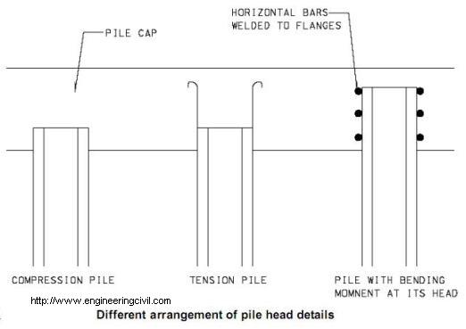
What are the head details of H-piles under compression and subject to bending moment?
For steel sections referred to in BS5950, universal bearing pile is characterized by having equal flange and web thickness while universal column has different flange and web thickness. Universal columns can also
be used as bearing piles.
In the design of the head details of H-piles, there are three typical cases to be considered, namely compression piles, tension piles and piles with bending moment at the head in addition to tension or compression. The design of these piles recommended by G. M. Cornfield (1968) is listed below:
(i) Compression piles
For this type of piles, H-piles should be embedded 150mm in concrete pile caps and it is not necessary to use any dowels and capping plates in their connection.
(ii) Tension piles
A number of hook-ended bars are welded to the top of H-piles.
(iii) Piles with bending moment at their head (tension or compression)
The depth of embedment of piles into pile caps is substantially increased and loads are transferred by horizontal bars welded to piles’ flanges.
This question is taken from book named – A Self Learning Manual – Mastering Different Fields of Civil Engineering Works (VC-Q-A-Method) by Vincent T. H. CHU.
What are the functions of different reinforcement in a typical pile cap?
Loads from columns transferring to pile cap induce tensile forces at the bottom of the cap. For instance, by using truss analogy to analyze a pile cap sitting on two piles with a column at the centre of the pile cap, the
tensile force at the bottom is proportional to the pile spacing and is inversely proportional to depth of pile cap. The bottom reinforcement is designed to resist the tensile stressed generated from loads in columns.
Side reinforcement may not be necessary in pile cap (L.A. Clark (1983)). In fact, the primary aim of the side reinforcement is to control cracking. However, as most pile caps are hidden from view and it is considered not necessary to provide side reinforcement to pile caps based on aesthetic reason.
Sometimes, reinforcement may be designed at the top of pile caps which serve as compression reinforcement. This type of reinforcement is required in case there is a limitation on the depth of pile caps. Similarly shear reinforcement is introduced to the pile caps in case there is a restriction to the depth of pile caps.
L. A. Clark (1983) Concrete Bridge Design to BS5400 Construction Press, Longman Group Limited pp.94
This question is taken from book named – A Self Learning Manual – Mastering Different Fields of Civil Engineering Works (VC-Q-A-Method) by Vincent T. H. CHU.
How does the pile installation method affect the load carrying capacity of piles?
The construction of piles by driving method causes an increase in density of the surrounding soils. Hence, for loose soils this results in improved compaction of soils between the piles. The sum of the capacities of all piles
as a whole is generally greater than the sum of individual pile capacities provided that the effect of pile spacing is not taken into account. However, for bored piles the boring operation induces considerable stress relief and
this causes a substantial reduction in shear strength of soils.
as a whole is generally greater than the sum of individual pile capacities provided that the effect of pile spacing is not taken into account. However, for bored piles the boring operation induces considerable stress relief and
this causes a substantial reduction in shear strength of soils.
Which of the following stages is noisier, at the ending of pile driving operation or at the end of pile driving operation?
When the piles are progressively driven into the ground, the pile section above the ground declines. As a result, the degree of damping on the piles increases. Moreover, the area of exposure of piling surface reduces, thereby reducing the area generating noise form piles. Hence towards the end of pile driving operation, the noise level shall be reduced accordingly.
Noise screen shall be installed to tackle the noise problem. Noise screen made of plywood might not be sufficient because it tends to reflect the noise back to the site and increase the reverberation of the site. Instead for the face of noise screen facing the piling operation shall be lined with a layer of sound-absorbing material such as glass fibre. Moreover, openings on noise screen should be avoided because it can substantially reduce the performance of noise screen.
This question is taken from book named – A Self Learning Manual – Mastering Different Fields of Civil Engineering Works (VC-Q-A-Method) by Vincent T. H. CHU.
In designing the lateral resistance of piles, should engineers only use the earth pressure against pile caps only?
In some design lateral loads are assumed to be resisted by earth pressure exerted against the side of pile caps only. However, it is demonstrated that the soil resistance of pile lengths do contribute a substantial part of lateral resistance. Therefore, in designing lateral resistance of piles, earth pressure exerted on piles should also be taken into consideration.
In analysis of lateral resistance provided by soils, a series of soil springs are adopted with modulus of reaction kept constant or varying with depth. The normal practice of using a constant modulus of reaction for soils is
incorrect because it overestimates the maximum reaction force and underestimates the maximum bending moment. To obtain the profile of modulus of subgrade reaction, pressuremeter tests shall be conducted in
boreholes in site investigation. Reference is made to Bryan Leach (1980).
This question is taken from book named – A Self Learning Manual – Mastering Different Fields of Civil Engineering Works (VC-Q-A-Method) by Vincent T. H. CHU.
Which one is a better choice, a large diameter piles or a system of several smaller piles with the same load capacity?
The choice of a large diameter pile suffers from the disadvantage that serious consequences would occur in case there is setting out error of the pile. Moreover, in terms of cost consideration, for the same load capacity the cost of a group of small diameter piles is generally lower than that of a large diameter pile. On the other hand, for small diameter piles i.e. mini-piles, they are advantageous in site locations with limited headroom and space. In addition, in some structures with only a few piles, it is uneconomic because of its high mobilization cost. Reference is made to Dr. Edmund C Hambly (1979).
This question is taken from book named – A Self Learning Manual – Mastering Different Fields of Civil Engineering Works (VC-Q-A-Method) by Vincent T. H. CHU.
This question is taken from book named – A Self Learning Manual – Mastering Different Fields of Civil Engineering Works (VC-Q-A-Method) by Vincent T. H. CHU.
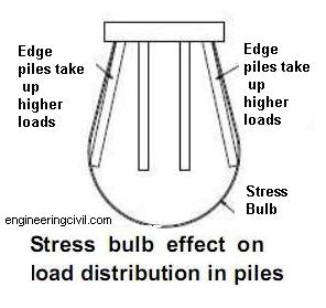
Do edge piles take up same loadings as central piles in rigid cap?
Due to the effect of interaction of individual piles, the central piles tend to settle more than the edge piles when the pile cap is under a uniform load. For the pile cap to be rigid, the local deformation of central piles would not occur. Instead, the stiff pile cap would transfer the loads from the central piles and redistribute them to the outer piles. Therefore, raking piles at the edge take up a higher fraction of the total loads and are subjected to higher axial and bending loads in case the pile cap is stiff. In the extreme case, the side piles may take up as much as about two to three times the loads in the central piles and this may lead to the failure of these raking edge piles.
There are several choices regarding the design to tackle the uneven distribution of loads. The first one involves the lengthening of side piles to stabilize the piles under high loads. However, the increased length of outer piles tends to attract more loads and this seems not to be a good solution. The other way out is to lengthen the central piles aiming at getting more loads and this evens out the load distribution among the piles
This question is taken from book named – A Self Learning Manual – Mastering Different Fields of Civil Engineering Works (VC-Q-A-Method) by Vincent T. H. CHU.
What are the differences between pinned bases and fixed bases?
When structures like portal frames are connected to the base foundation, engineers have to decide the degree of fixity for the connection. In general, the two common design options are pinned bases and fixed bases. Pinned bases have the advantage that the design of foundation is made simple so that some cost savings may result. However, fixed bases design provides additional rigidity and stiffening to the structures and the stability of the structures can be enhanced. Therefore, the use of fixed bases helps to improve the structural performance of the structures
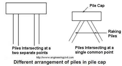
How should the piles be arranged in a pile cap to reduce bending moment induced in piles?
Consider that piles are designed to intersect at a single common point in a pile cap. The resultant reactions would pass through the point of intersection in the pile cap. This type of arrangement does not involve any
bending moment induced if the horizontal loads pass through this point. However, in real life situation, the piling system is expected to resist a combination of vertical loads, horizontal loads and bending moment. To
counteract bending moment, the pile cap about the point of intersection is rotated so that significant amount of bending moment is induced in piles and pure axial forces in piles can hardly generate a counteracting moment based on one single intersection point.
However, if the piles are arranged in such a way that there are at least two separated points of intersection in the pile cap, the amount of flexural stresses induced in piles is significantly reduced.
This question is taken from book named – A Self Learning Manual – Mastering Different Fields of Civil Engineering Works (VC-Q-A-Method) by Vincent T. H. CHU.
In some pile design, the settlement of piles are not checked. Is it correct?
The performance of piles mainly consists of the two elements, namely ultimate bearing capacity and settlement. The local practice of pile design is place emphasis on checking if the bearing capacity of piles would be exceeded.
Engineers tend to adopt the approach that bored piles are designed to be founded on bedrock while for driven piles they are driven to very stiff stratum with SPT N values greater than 200. Owing to rigid and firm
foundation on which the piles are seated, it is therefore assumed that the amount of settlement shall be limited. On the other hand, there is practical difficulty in assessing how much settlements are considered acceptable owing to limited available data.
This question is taken from book named – A Self Learning Manual – Mastering Different Fields of Civil Engineering Works (VC-Q-A-Method) by Vincent T. H. CHU.
Which type of pile cap transfers loads equally to piles, flexible pile cap or rigid pile cap?
Loads from columns transferring to pile cap induce tensile forces at the bottom of the cap. For instance, by using truss analogy to analyze a pile cap sitting on two piles with a column at the centre of the pile cap, the
tensile force at the bottom is proportional to the pile spacing and is inversely proportional to depth of pile cap. The bottom reinforcement is designed to resist the tensile stressed generated from loads in columns.
Sometimes, reinforcement may be designed at the top of pile caps which serve as compression reinforcement. This type of reinforcement is required in case there is a limitation on the depth of pile caps. Similarly shear reinforcement is introduced to the pile caps in case there is a restriction to the depth of pile caps. Consider that loads are applied at the centre of a pile cap.
For the case of rigid pile cap, owing to the effect of interaction of individual piles, the central piles tend to settle more than the edge piles when the pile cap is under loading condition. For the pile cap to be rigid, the local deformation of central piles would not occur. Instead, the stiff pile cap would transfer the loads from the central piles and redistribute them to the outer piles. Therefore, piles at the edge take up a higher fraction of the total loads and are subjected to higher axial and bending loads in case the pile cap is stiff. In the extreme case, the side piles may take up as much as about two to three times the loads in the central piles and this may lead to the failure of these edge piles.
For flexible pile cap, load taken up by individual piles are different because the deformation of pile cap enhances non-uniform distribution of loads among piles. The piles closer to the load tend to share more loads when compared with those which are located far away from the loads. The difference of loads induced in piles increase with the flexibility of pile cap.
This question is taken from book named – A Self Learning Manual – Mastering Different Fields of Civil Engineering Works (VC-Q-A-Method) by Vincent T. H. CHU.
In modeling a nonrigid mat foundation by using elastic springs, should a uniform modulus of subgrade reaction be used along the whole base of mat?
By using a bed of springs to simulate the flexible behaviour of mat subject to loads, care should be taken in selection of the modulus of subgrade reaction. In fact, the modulus of subgrade reaction depends on many
factors like the width of the mat, the shape of the mat, the depth of founding level of the mat etc. In particular, the modulus of subgrade reaction is smaller at the center while it is larger near the mat’s edges. If a constant modulus of subgrade reaction is adopted throughout the width of the mat, then a more or less uniform settlement will result when subject to a uniform load. However, the actual behaviour is that settlement in the center is higher than that at side edges. Consequently, it leads to an underestimation of bending moment by 18% to 25% as suggested by Donald P. Coduto (1994).
In general, a constant value of modulus of subgrade reaction is normally applied for structure with a rigid superstructure and the rigid foundation. However, a variable modulus of subgrade reaction is adopted instead for non-rigid superstructure and non-dominance of foundation rigidity to account for the effect of pressure bulbs.
This question is taken from book named – A Self Learning Manual – Mastering Different Fields of Civil Engineering Works (VC-Q-A-Method) by Vincent T. H. CHU.
What is the purpose of setting maximum spacing of piles?
One of the factors that affect the distribution of loads from the structures to each pile is the assumption of flexibility of the pile caps in design. A pile cap can be modeled as a flexible or a rigid element based on their relative stiffness. For the pile cap to be assumed as rigid the stiffness of pile cap is infinite relative to that of pile/soil system and the deformations within the cap are not considered owing to its rigidity. On the other hand, for the pile cap to be designed as flexible, internal deformations of pile cap would occur.
In some design guidelines, maximum spacing of piles is specified to limit the length between adjacent piles so that the assumption of rigid pile cap can be justified.
This question is taken from book named – A Self Learning Manual – Mastering Different Fields of Civil Engineering Works (VC-Q-A-Method) by Vincent T. H. CHU.
What is the difference between capping beams and ground beams for piles?
Capping beams for piles aim at transferring loads from closely spaced columns or walls into a row of piles. On the other hand, ground beams are beams provided between adjacent pile caps and they perform as compression struts or ties in an attempt to prevent lateral displacement or buckling of piles under uneven distribution of loads on pile caps. Both of them have to be specially designed to cater for differential settlement of piles.
Capping beam performs the same functions as pile caps. However, ground beams are structural elements to connect adjacent pile caps to improve the stability of foundation.
This question is taken from book named – A Self Learning Manual – Mastering Different Fields of Civil Engineering Works (VC-Q-A-Method) by Vincent T. H. CHU.
What are the differences in function between rock anchors and rock sockets?
Rock anchors are used primarily for resisting uplift forces. On the contrary, rock sockets serve three main purposes:
(i) Rock socket friction and end bearing to resist vertical load.
(ii) Passive resistance of rock sockets contribute to resistance of lateral load.
(iii) Socket shaft friction is also used for resisting uplifting forces. But only 70% of this capacity should be used because of the effect of negative Poisson ratio.
Note: Rock anchors, which may consist of a high tensile bar or a stranded cable, are provided for tension piles when there are insufficient soil covers to develop the required uplifting resistance.
This question is taken from book named – A Self Learning Manual – Mastering Different Fields of Civil Engineering Works (VC-Q-A-Method) by Vincent T. H. CHU.
What are the limitations of Plate Load Test?
Plate load test is carried out to check the bearing capacity of foundation soils.
The limitations of plate load test are:
(i) It has limited depth of influence. It could only give the bearing capacity of soils with depth up to two times the diameter of plate.
(ii) It may not provide information on the potential for long term consolidation of foundation soils.
(iii) There is scale effect as the size of test plate is smaller than actual foundation.
(iv) To gain access to test position, excavation is carried out which causes significant ground disturbance. The change in ground stress leads to the change of soil properties which the test is planned to investigate.
This question is taken from book named – A Self Learning Manual – Mastering Different Fields of Civil Engineering Works (VC-Q-A-Method) by Vincent T. H. CHU.
Can both Pile Drive Analyser PDA and Pile Integrity Test PIT be used for checking pile capacity?
Pile Drive Analyser is a high-strain dynamic test to determine the force and velocity response of a pile to an impact force applied axially by a driving hammer at the pile top. It is applicable to driven piles or small diameter bored piles. The operation measures the elastic deformation of a pile after a hammer blow and is mainly used to check the ultimate capacity of piles. However, it may also be adopted to detect damages in pile body and obtain the friction profile along the pile shaft.
Pile Integrity Test is a low-strain dynamic test which involves the use of a small vibrator or a light hammer. It is applicable to small diameter driven concrete piles and large diameter bored piles. It can be used to check the following properties:
(i) Quality of concrete (e.g. honeycombing)
(ii) Location and type of damages
(iii) Estimation of pile length
However, it is mainly used to check the integrity of piles only and it may be used to deduce the pile capacity.
This question is taken from book named – A Self Learning Manual – Mastering Different Fields of Civil Engineering Works (VC-Q-A-Method) by Vincent T. H. CHU.
What is the difference between point of virtual fixity and critical length of lateral loading for piles?
Some engineers may get confused about the difference between the two terms i.e. point of virtual fixity and critical length used for piles for resisting lateral loads. For critical length of lateral loading for piles, it refers to a certain depth from the ground level where the piles behave as if it were infinitely long. As such, beyond the critical length, the change in lateral response of piles with increase in pile length will be negligible.
Point of virtual fixity refers to a certain dept below ground surface where the piles are fixed without movement under loads. The depth to the point of fixity is useful in assessing the buckling loads of piles. It is obvious that the depth to the point of virtual fixity should be smaller than the critical length of piles.
Point of virtual fixity refers to a certain dept below ground surface where the piles are fixed without movement under loads. The depth to the point of fixity is useful in assessing the buckling loads of piles. It is obvious that the depth to the point of virtual fixity should be smaller than the critical length of piles.
What are the meanings of the mathematical terms in failure criteria pile load test?
Load tests are conducted to verify the design assumptions and parameters such as pile friction in soils and sock socket capacity. There are various failure criteria in current construction industry to determine ultimate load resistance of piles in pile load test. For instance in 90% criterion of Brinch Hansen, it is based on the laboratory measured stress-strain relations of soils and a point is identified in which soil fails. This essentially aims at looking for the ultimate bearing capacity and hence the ultimate loads. In fact, this is not intended originally for piles.
For some failure criteria, it does not target at finding out the ultimate pile capacity. Instead, it looks for the process for onset of soil yielding at the base of pile toe an allows for controlled displacement. For example, one of these criteria is reproduced as follows:
Criterion for maximum movement = (PL/AE + d/120 + 4) mm
where P is the load, L is pile length, A is the area of pile and d is pile diameter.
This failure criterion was developed based on small diameter driven piles. The term PL/AE refers to elastic shortening of piles. For end-bearing piles, this term is acceptable for usage. However, for friction piles this may not truly simulate the actual shortenings of piles because frictional forces along the pile also come into play. The term (d/120 + 4) represents the amount of soil movement which triggers the yielding of soil beneath pile toe.
This question is taken from book named – A Self Learning Manual – Mastering Different Fields of Civil Engineering Works (VC-Q-A-Method) by Vincent T. H. CHU.
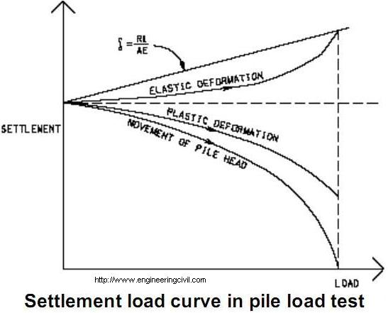
What is the purpose of conducting load test for piling works?
Pile load test provides information on ultimate bearing capacity but not settlement behavior. In essence, it can determine if the load is taken up by the stratum designed or if the centre of resistance is at the design location in piles as suggested by Robert D. Chellis (1961).
After conducting load tests, the curve of movement of pile head (Settlement against load) and the curve of plastic deformation can be plotted. By subtracting the curve of plastic deformation from the curve of pile head movement at each load, the curve of elastic deformation can be obtained. For piles of end-bearing type unrestrained by friction, the theoretical elastic deformation can be calculated from e=RL/AE where e is
elastic deformation, L is pile length, A is area of pile, E is Young’s Modulus of pile material and R is the reaction load on pile. By substituting e in the formula, the elastic deformation read from the curve of elastic deformation, L can be obtained which shows the location of the centre of resistance corresponding to that load.
This question is taken from book named – A Self Learning Manual – Mastering Different Fields of Civil Engineering Works (VC-Q-A-Method) by Vincent T. H. CHU.
There is an old rule that the area of a follower should be one-fifth of precast concrete pile. Why?
The rules of wave mechanics suggested that to avoid reflection of stress wave caused by different impedance values, acoustic impedance should be the same for the follower and precast concrete piles. As such, it enhances smoothest driving and prevent follower from bouncing on the head of piles which is undesirable as it may damage the piles and lowers the efficiency of driving.
Acoustic impedance = Elastic Modulus (E) x Area of Pile / wave velocity
Wave velocity (c) = Elastic Modulus / Density of Pile
For normal steel, E=205GPa, c=5,100m/s
For normal concrete, E=30GPa, c=3,800m/s
For same acoustic impedance,
Area of concrete/Area of steel = (205/5,100)/(30/3,800) = 5
This question is taken from book named – A Self Learning Manual – Mastering Different Fields of Civil Engineering Works (VC-Q-A-Method) by Vincent T. H. CHU.
In the installation of strain gages in driven H-piles to measure loads, why should they be normally used in pairs?
Strain gages are often installed in driven piles to measure the load distribution along the piles. They have to be protected from being removed as the pile is driven into the ground. Protection of strain gages is achieved by welding channels or angles for enclosure of stain gages.
Strain gages should always be installed in pairs located back to back on the same piece of steel. For instance they may be placed back to back on either side of web of H-piles. Only one gage mounted on the cross section of H-pile is not too useful because it may be affected by an unknown degree by bending moment. Hence, the results of axial load may appear to be doubtful.
This question is taken from book named – A Self Learning Manual – Mastering Different Fields of Civil Engineering Works (VC-Q-A-Method) by Vincent T. H. CHU.
How can piles be driven through steeply dipping karst surfaces?
The steep dipping and variable nature of karst surfaces poses problems for installation of driven piles. Very often, the consequences of hard driving piles over steeply-inclined karst are slipping and buckling of piles. To tackle these problems, the following two options are mostly adopted:
(i) Pre-boring is carried out in steep dipping karst surface as this method could penetrate hard layers;
(ii) Reinforcing the end section of driven piles by welding stiffening plates
This question is taken from book named – A Self Learning Manual – Mastering Different Fields of Civil Engineering Works (VC-Q-A-Method) by Vincent T. H. CHU.
Interesting investing site about engineering
ReplyDeleteBuy Building Material Online, Cement, TMT Bar, Electrical, Plumbing, Doors, Lighting, Flooring, Paints, Bricks & Best Prices in Hyderabad on RippleMart
ReplyDeletehttps://www.ripplemart.com/
Great post on pile engineering! The concepts are well explained and connect well with diaphragm wall techniques. Bhagwati Machinery appreciates such valuable civil engineering content—thanks!
ReplyDelete