Give Introduction of Contouring
Contouring is the science of representing the vertical dimension of the terrain on a two dimensional map. We can understand contouring by considering a simple example.
Let us assume that a right circular cone of base 5m diameter and vertical height 5m is standing upright on its base. Let the base be resting on a horizontal plane at zero level as shown in Figure 1.
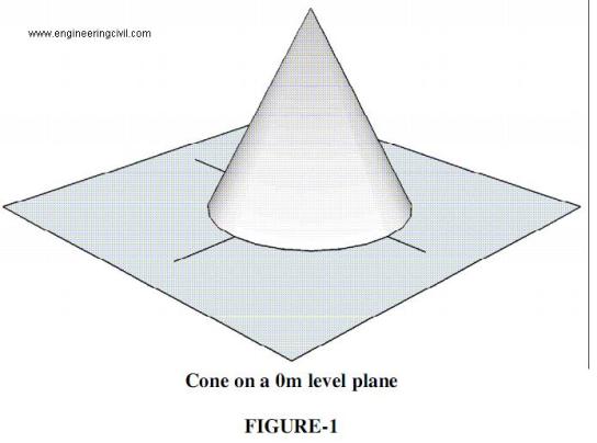
At zero level, the outline of the cone will be a circle of 5m diameter. This circle is the contour line at 0m elevation for the cone. We draw this first contour line on paper to a convenient scale.
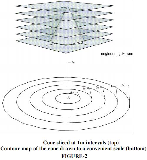
Let us now slice the cone at 1m height from the base. This will produce another circular outline corresponding to the diameter of the cone at 1m elevation. Let us draw this second circle on our contour map using the same scale. The second circle being smaller in diameter than the first will appear as a concentric circle within the first circle.
Similarly, we continue to draw the outline of the cone at 2m, 3m, 4m and 5m levels on our contour map. Our contour map for the conical object is now ready. The circles on the map are called contour lines. (see figure-2)
Like the cone in our example, hills project upwards from ground level. The contour map of a hilly terrain will be similar to that of the cone, except that instead of perfect circles, the contour lines would be of
irregular shapes. The important point of similarity to note here is that hilly terrain would be represented by contour lines with increasing elevation towards the centre.
In contrast to this, a pond or depression would be represented by contour lines with decreasing elevation towards the centre.
We at engineeringcivil.com are thankful to Mr Ramasesh Iyer for submitting this useful information to us.
Let us assume that a right circular cone of base 5m diameter and vertical height 5m is standing upright on its base. Let the base be resting on a horizontal plane at zero level as shown in Figure 1.
At zero level, the outline of the cone will be a circle of 5m diameter. This circle is the contour line at 0m elevation for the cone. We draw this first contour line on paper to a convenient scale.
Let us now slice the cone at 1m height from the base. This will produce another circular outline corresponding to the diameter of the cone at 1m elevation. Let us draw this second circle on our contour map using the same scale. The second circle being smaller in diameter than the first will appear as a concentric circle within the first circle.
Similarly, we continue to draw the outline of the cone at 2m, 3m, 4m and 5m levels on our contour map. Our contour map for the conical object is now ready. The circles on the map are called contour lines. (see figure-2)
Like the cone in our example, hills project upwards from ground level. The contour map of a hilly terrain will be similar to that of the cone, except that instead of perfect circles, the contour lines would be of
irregular shapes. The important point of similarity to note here is that hilly terrain would be represented by contour lines with increasing elevation towards the centre.
In contrast to this, a pond or depression would be represented by contour lines with decreasing elevation towards the centre.
We at engineeringcivil.com are thankful to Mr Ramasesh Iyer for submitting this useful information to us.
Explain Terms Used in Contouring
Define Contour Line
A Contour line is an imaginary outline of the terrain obtained by joining its points of equal elevation. In our example of the cone, each circle is a contour line joining points of same level.
Define Contour Interval (CI)
Contour interval is the difference between the levels of consecutive contour lines on a map. The contour interval is a constant in a given map. In our example, the contour interval is 1m.
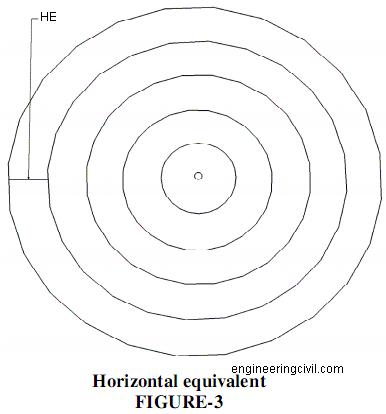
Define Horizontal Equivalent (HE)
Horizontal equivalent is the horizontal distance between two consecutive contour lines measured to the scale of the map.
Gradient
Gradient represents the ascending or descending slope of the terrain between two consecutive contour lines. The slope or gradient is usually stated in the format 1 in S, where 1 represents the vertical component of the slope and S its corresponding horizontal component measured in the same unit.
The gradient between two consecutive contour lines can also be expressed in terms of Tan Q(theta) as follows:
Tan Q (theta) = CI / HE … both measured in the same unit.
We at engineeringcivil.com are thankful to Mr Ramasesh Iyer for submitting this useful information to us.
A Contour line is an imaginary outline of the terrain obtained by joining its points of equal elevation. In our example of the cone, each circle is a contour line joining points of same level.
Define Contour Interval (CI)
Contour interval is the difference between the levels of consecutive contour lines on a map. The contour interval is a constant in a given map. In our example, the contour interval is 1m.
Define Horizontal Equivalent (HE)
Horizontal equivalent is the horizontal distance between two consecutive contour lines measured to the scale of the map.
Gradient
Gradient represents the ascending or descending slope of the terrain between two consecutive contour lines. The slope or gradient is usually stated in the format 1 in S, where 1 represents the vertical component of the slope and S its corresponding horizontal component measured in the same unit.
The gradient between two consecutive contour lines can also be expressed in terms of Tan Q(theta) as follows:
Tan Q (theta) = CI / HE … both measured in the same unit.
We at engineeringcivil.com are thankful to Mr Ramasesh Iyer for submitting this useful information to us.
What is the Difference Between Contour Interval and Horizontal Equivalent
There are three main differences between contour interval and horizontal equivalent as follows:
We at engineeringcivil.com are thankful to Mr Ramasesh Iyer for submitting this useful information to us.
| S.No | Contour Interval | Horizontal Equivalent |
| 1 | It is based on vertical levels | Represents horizontal distance |
| 2 | No measurement or scaling is required since the contour levels are indicated on the contour lines | The distance must be measured on the map and converted to actual distance by multiplying with the scale of the map |
| 3 | In a given map the contour interval is a constant | The horizontal equivalent varies with slope. Closer distance indicates steep slope and wider distance gentle slope |
What are the factors governing Selection of Contour Intervals?
The survey leader has to decide an appropriate contour interval for his project before start of survey work. The following factors govern the selection of contour interval for a project:
We at engineeringcivil.com are thankful to Mr Ramasesh Iyer for submitting this useful information to us.
| S.No | Factor | Select High CI like 1m, 2m, 5m or more | Select Low CI like 0.5m, 0.25m, 0.1m or less |
| 1 | Nature of ground | If the ground has large variation in levels, for instance, hills and ponds | If the terrain is fairly level |
| 2 | Scale of the map | For small scale maps covering a wide area of varying terrain | For large scale maps showing details of a small area |
| 3 | Extent of survey | For rough topographical map meant for initial assessment only | For preparation of detailed map for execution of work |
| 4 | Time and resources available | If less time and resources are available | If more time and resources are available |
What are the Characteristics of Contours?
Contours show distinct characteristic features of the terrain as follows:
i) All points on a contour line are of the same elevation.
ii) No two contour lines can meet or cross each other except in the rare case of an overhanging vertical cliff or wall
iii) Closely spaced contour lines indicate steep slope
iv) Widely spaced contour lines indicate gentle slope
v) Equally spaced contour lines indicate uniform slope
vi) Closed contour lines with higher elevation towards the centre indicate hills
vii) Closed contour lines with reducing levels towards the centre indicate pond or other depression.
viii) Contour lines of ridge show higher elevation within the loop of the contours. Contour lines cross ridge at right angles.
ix) Contour lines of valley show reducing elevation within the loop of the contours. Contour lines cross valley at right angles.
x) All contour lines must close either within the map boundary or outside.
What are the Uses of Contours?
Contour maps are very useful since they provide valuable information about the terrain. Some of the uses are as follows:
i) The nature of the ground and its slope can be estimated
ii) Earth work can be estimated for civil engineering projects like road works, railway, canals, dams etc.
iii) It is possible to identify suitable site for any project from the contour map of the region.
iv) Inter-visibility of points can be ascertained using contour maps. This is most useful for locating communication towers.
v) Military uses contour maps for strategic planning.
We at engineeringcivil.com are thankful to Mr Ramasesh Iyer for submitting this useful information to us.
What are the methods of Contouring?
Two methods of Contouring are:-
i) DIRECT METHOD
ii) INDIRECT METHOD
DIRECT METHOD
In direct method, the points of equal elevation on the terrain are physically located and then plotted on map. This is a very tedious process and requires more time and resources than the indirect method.
INDIRECT METHOD
In the indirect method of contouring on of these three methods are adopted:
A) Cross Section Method
B) Squares Or Grid Method
C) Tacheometric Method
We at engineeringcivil.com are thankful to Mr Ramasesh Iyer for submitting this useful information to us.
Explain Cross Section Method of Contouring?
Cross section method is most suitable for preparing contour maps for road works, rail works, canals etc.
Typically, this type of land has a very long strip but narrow width.
The steps involved are as follows:
i) The centre line of the strip of land is first marked
ii) Lines perpendicular to the longitudinal strip are marked dividing the strip into equal sections
iii) The perpendicular lines are divided into equally spaced divisions, thus forming rectangular grids.
iv) Levels are taken at the intersection of the grid lines to obtain the cross-section profile of the strip of land.
v) Contour map is plotted in the office by interpolating points of equal elevation based on the levels taken at site.
We at engineeringcivil.com are thankful to Mr Ramasesh Iyer for submitting this useful information to us.
Explain Squares or Grid Method of Contouring?
Squares or grid method is suitable for contouring of plains or gently sloping grounds.
The steps adopted are as follows:
i) Mark square grids on the land to be surveyed. The grid size would depend on the extent of survey.
Generally a 1m x 1m grid is selected for small works and a larger grid size for large works
ii) Levels are taken at all the corners of the square and the intersection of the diagonal.
iii) Levels taken on the intersection of diagonals is used for verification of the interpolation.
vi) Contour map is plotted in the office by interpolating points of equal elevation based on the levels taken on the corners of the square.
We at engineeringcivil.com are thankful to Mr Ramasesh Iyer for submitting this useful information to us.
Explain Tacheometric Method of Contouring?
Tacheometric method is adopted for contouring of very steep hills.
The steps are as follows:
i) Set up the tacheometer at the top of the steep hill. Tacheometer is a theodolite fitted with stadia diaphragm. The stadia diaphragm has three horizontal parallel hairs instead of one as found in a conventional cross hair diaphragm.
ii) With the help of a tacheometer it is possible to determine the horizontal distance of the point from the telescope as well its vertical level.
iii) The steep hill is surveyed at three levels – the base of the hill, the mid-level of the hill and the top level of the hill.
iv) Using the tacheometer reading are taken all around the hill at equal angular intervals on all these three
levels.
v) The radial plot thus obtained is worked in the office to interpolate points of equal elevation for contour mapping.
Compare Direct and Indirect Contouring Methods
The Comparison of Direct and Indirect Contouring Methods is shown below in tabular form
We at engineeringcivil.com are thankful to Mr Ramasesh Iyer for submitting this useful information to us.
| S No | Direct Method | Indirect Method |
| 1 | Very tedious | Not tedious |
| 2 | Accurate | Less accurate |
| 3 | Slow | Fast |
| 4 | Requires more resources | Requires less resources |
| 5 | Suitable for contouring of small area. | Suitable for large areas |
| 6 | Points are physically located on the ground | Points are interpolated in the office |
How to determine Area of Field using Cross Staff Survey?
Object: – To determine area of field using cross staff survey.
Equipments: -
1. Ranging rod – 7 Nos.
2. 30 m Chain – 1 Nos.
3. Arrow – 5 Nos.
4. Metallic tape (30m) – 1 Nos.
5. Cross staff with stand – 1 Nos.
Procedure: -
1. Field work
2. Classroom work
(1.) Field work
1. First of all first ranging rod is established at point A and makes fixed station taking measurement revising point A to two permanent structures.
2. Second ranging rod is established at point B and for makes fixed station taking measurement revising point B to two permanent structures.
3. Established grid line A to B using ranging procedure by judgment of eye and laying chain on it.
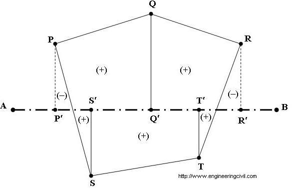
4. Remaining ranging rod established at point P, Q, R, and S, T on right and left side of the grid line and its may be point of permanent structure at different location.
5. Sight point P perpendicular to grid line using cross staff, let’s meeting point is P’ on grid line.
6. Measure distance of AP’ and PP’ by chain (on grid line) and metallic tape (between P to P’).
7. Write all observation in field book or level book immediately.
8. Repeat Sighting procedure using cross staff, let’s meeting point is Q’, R’, S’, and T’ on grid line.
9. Measure distance of AQ’, AR’, AS’ and AT’ by chain (on grid line) and QQ’, RR’, SS’, TT’ using Metallic tape respectively.
10. Write all observation in field book or level book respectively.
11. When complete all observation removes all ranging rods and packed in its cover.
(2) Classroom work: -
1. Draw a complete figure in field book using field observation.
2. Draw a line meeting point P to S and R to T on field book or level book.
3. Calculate the area of field by subtract out side (remaining) area of meeting line in total area in field book
Observation table: -
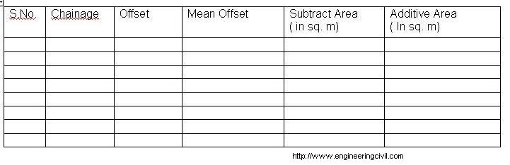
Figure: –
Precautions: –
1. The ranging rod should be established correctly state at all points.
2. The judgment of line should be taking correctly during established ranging rod at a point.
3. Distance between surveyor’s eye and reference station (eg. A, B and C) should be minimum one meter.
4. The cross staff should be states during sight both station and observations take accurately.
We are thankful to Er. Praveen Kumar Pandey for submitting this very useful topic to us.
Equipments: -
1. Ranging rod – 7 Nos.
2. 30 m Chain – 1 Nos.
3. Arrow – 5 Nos.
4. Metallic tape (30m) – 1 Nos.
5. Cross staff with stand – 1 Nos.
Procedure: -
1. Field work
2. Classroom work
(1.) Field work
1. First of all first ranging rod is established at point A and makes fixed station taking measurement revising point A to two permanent structures.
2. Second ranging rod is established at point B and for makes fixed station taking measurement revising point B to two permanent structures.
3. Established grid line A to B using ranging procedure by judgment of eye and laying chain on it.
4. Remaining ranging rod established at point P, Q, R, and S, T on right and left side of the grid line and its may be point of permanent structure at different location.
5. Sight point P perpendicular to grid line using cross staff, let’s meeting point is P’ on grid line.
6. Measure distance of AP’ and PP’ by chain (on grid line) and metallic tape (between P to P’).
7. Write all observation in field book or level book immediately.
8. Repeat Sighting procedure using cross staff, let’s meeting point is Q’, R’, S’, and T’ on grid line.
9. Measure distance of AQ’, AR’, AS’ and AT’ by chain (on grid line) and QQ’, RR’, SS’, TT’ using Metallic tape respectively.
10. Write all observation in field book or level book respectively.
11. When complete all observation removes all ranging rods and packed in its cover.
(2) Classroom work: -
1. Draw a complete figure in field book using field observation.
2. Draw a line meeting point P to S and R to T on field book or level book.
3. Calculate the area of field by subtract out side (remaining) area of meeting line in total area in field book
Observation table: -
Figure: –
Precautions: –
1. The ranging rod should be established correctly state at all points.
2. The judgment of line should be taking correctly during established ranging rod at a point.
3. Distance between surveyor’s eye and reference station (eg. A, B and C) should be minimum one meter.
4. The cross staff should be states during sight both station and observations take accurately.
We are thankful to Er. Praveen Kumar Pandey for submitting this very useful topic to us.
How to Plot Building Block by the use of Cross Staff?
Object: – Plotting building block by the use of cross staff.
Equipments: -
1. Ranging rod – 3 Nos.
2. 30 m Chain – 1 Nos.
3. Arrow – 5 Nos.
4. Metallic tape (30m) – 1 Nos.
5. Cross staff with stand – 1 Nos.
Procedure: -
1. First of all first ranging rod is established at point A and makes fixed station taking measurement revising point A to two permanent structures.
2. Second ranging rod is established at point B and for makes fixed station taking measurement revising point B to two permanent structures.
3. Established grid line A to B using ranging procedure by judgment of eye and laying chain on it.
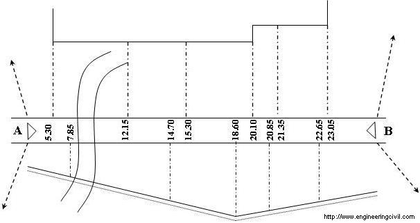
4. Remaining ranging rod established at exiting corner of object and sight by open cross staff. Let’s meeting point is P.
5. Measure distance of AP and P to sighted object by chain (on grid line) and metallic tape (between P to sighted object).
6. Next object sighted by cross staff in both directions to grid line.
7. Distance between objects to meeting point is noted in field as well as on grid line.
8. Repeat the process until completion the work.
9. Plot plan of field condition or building block by help of field observation.
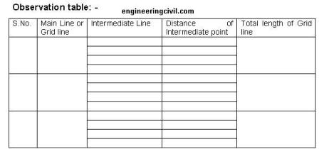
Observation table: -
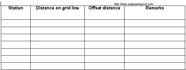
Figure:
Precautions: -
1. The ranging rod should be established correctly state at all points.
2. The judgment of line should be taking correctly during established ranging rod at a point.
3. Distance between surveyor’s eye and reference station (eg. A, B and C) should be minimum one meter.
4. The cross staff should be states during sight both station and observations take accurately.
We are thankful to Er. Praveen Kumar Pandey for submitting this very useful topic to us.
Equipments: -
1. Ranging rod – 3 Nos.
2. 30 m Chain – 1 Nos.
3. Arrow – 5 Nos.
4. Metallic tape (30m) – 1 Nos.
5. Cross staff with stand – 1 Nos.
Procedure: -
1. First of all first ranging rod is established at point A and makes fixed station taking measurement revising point A to two permanent structures.
2. Second ranging rod is established at point B and for makes fixed station taking measurement revising point B to two permanent structures.
3. Established grid line A to B using ranging procedure by judgment of eye and laying chain on it.
4. Remaining ranging rod established at exiting corner of object and sight by open cross staff. Let’s meeting point is P.
5. Measure distance of AP and P to sighted object by chain (on grid line) and metallic tape (between P to sighted object).
6. Next object sighted by cross staff in both directions to grid line.
7. Distance between objects to meeting point is noted in field as well as on grid line.
8. Repeat the process until completion the work.
9. Plot plan of field condition or building block by help of field observation.
Observation table: -
Figure:
Precautions: -
1. The ranging rod should be established correctly state at all points.
2. The judgment of line should be taking correctly during established ranging rod at a point.
3. Distance between surveyor’s eye and reference station (eg. A, B and C) should be minimum one meter.
4. The cross staff should be states during sight both station and observations take accurately.
We are thankful to Er. Praveen Kumar Pandey for submitting this very useful topic to us.
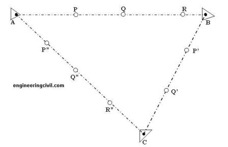
Ranging and Fixing Of Survey Station
The object of this experiment is to set up a survey station. This is the basic step of surveying but this is also the one which has the maximum number of errors.
The Equipments used for this are :-
1. Ranging rod …………5 Nos. (min).
2. 30 m Chain…………..1 Nos.
3. Arrow…………………5 Nos. (min.)
The Procedure to conduct is as follow :
(Ranging by eye)
1. First of all first ranging rod is established at known point A and its ranging rod should be fixed at point A up to completion of work.
2. Second ranging rod is established at known point B (or at known object) and a ranging rod should be fixed at point B up to completion of work.
3. Third ranging rod established at point P (or any) approximately on the line of point AB (by judgment) and it’s not greater than one chain length from point A.
4. Measure the distance of AP by chain and move ranging rod at point P to its next position and establishing a wooden peg or arrow at point P.
5. Third ranging is established at point Q (or any) approximately on the line of point AB (by judgment) and it’s not greater than one chain length from point P.
6. Measure the distance of PQ by chain and move ranging rod at point Q to its next position and establishing a wooden peg or arrow at point Q.
7. Its procedure repeats up to reaching point B.
8. Third ranging rod is established at known point C (or at known object) and a ranging rod should be fixed at point C up to completion of work.
9. Fourth ranging rod established at point P’ (or any) approximately on the line of point BC (by judgment) and it’s not greater than one chain length from point B.
10. Measure the distance of BP’ by chain and move ranging rod at point P’ to its next position and establishing a wooden peg or arrow at point P’.
11. Fourth ranging is established at point Q’ (or any) approximately on the line of point BC (by judgment) and it’s not greater than one chain length from point P’.
12. Measure the distance of P’Q’ by chain and move ranging rod at point Q’ to its next position and establishing a wooden peg or arrow at point Q’.
13. Its procedure repeats up to reaching point C.
14. Fifth ranging rod established at point P” (or any) approximately on the line of point CA (by judgment) and it’s not greater than one chain length from point C.
15. Measure the distance of CP” by chain and move ranging rod at point P” to its next position and establishing a wooden peg or arrow at point P”.
16. Fifth ranging is established at point Q” (or any) approximately on the line of point CA (by judgment) and it’s not greater than one chain length from point P”.
17. Measure the distance of P”Q” by chain and move ranging rod at point Q” to its next position and establishing a wooden peg or arrow at point Q”.
18. Its procedure repeats up to reaching point A.
19. Finally complete a triangle and position of point A, B, and C is known respect to each other.
Precautions: –
1. The ranging rod should be established correctly state at all points.
2. The judgment of line should be taking correctly during established ranging rod at a point.
3. Distance between surveyor’s eye and reference station (eg. A, B and C) should be minimum one meter.
What is Photogrammetry?
Photogrammetry is a technique used in surveying to measure the three dimensional coordinates with the help of photography. It is used for the purpose of measurements.
Fundamental Principle
Triangulation is the fundamental principle used by photogrammetry. In this technique, we take photographs from atleast two different locations. The purpose of taking pictures from more than 2 points is to create what engineers call “lines of sight.” Once these lines of sight are prepared, we join them to locate a point where they meet and thus calculate the coordinates of the desired point.
Measurement of distance with tapes
Precisions for different methods of measuring distances are given below:-
Pacing (ordinary terrain): 1/50 to 1/100
Taping (ordinary steel tape): 1/1000 to 1/10,000.
Baseline (invar tape): 1/50,000 to 1/1,000,000
Stadia: 1/300 to 1/500
Subtense bar: 1/1000 to 1/7000
Now with technological advances, a technique called Electronic distance measurement or EDM is replacing the use of steel tapes as they are much more precise then steel tapes.
Units of Measurement
Units of measurement used in past and present surveys are
For construction work: feet, inches, fractions of inches (m, mm)
For most surveys: feet, tenths, hundredths, thousandths (m, mm)
For National Geodetic Survey (NGS) control surveys: meters, 0.1, 0.01, 0.001 m
For construction work: feet, inches, fractions of inches (m, mm)
For most surveys: feet, tenths, hundredths, thousandths (m, mm)
For National Geodetic Survey (NGS) control surveys: meters, 0.1, 0.01, 0.001 m
What are the Corrections Applied in Surveying?
For surveying, we need to have some prerequisite conditions. If these conditions are not met we can have a huge variation in result. Therefore we have to apply corrections to get the true result.
Ideal Conditions
1) A tape accurate to 0.00305m or 0.01 ft should be used.
2) Tension of the tape should be about 66.7N or 15 lb.
3) Temperature should be determined within 5.56°C or 10°F
4) The slope of the ground, should be within 2 percent
On ground these are nearly impossible to achieve and thus corrections need to be applied.
Continue Reading »
What is Orthometric Correction?
We know that earth flattens in the polar direction and this curvature of earth is responsible for the departure of horizontal line from a level surface. To counter this error, orthometric corrections is applied.
This departure in feet, Cf is calculated as
Cf= 0.667M2=0.0239F2
This departure in meters, Cm is calculated
Cm =0.0785K 2
where M = distances in miles from the point of tangency to the earth.
F= distances in thousands of feet from the point of tangency to the earth.
K = distances in kilometers from the point of tangency to the earth.
How To Play Emperor Casino | Shootercasino
ReplyDeletePlay Emperor Casino games in a variety of different game modes such as slots, live dealer, 제왕 카지노 도메인 online poker, bingo and live dealer.