Study The Contribution In The Additions Mineral On The Paste, Mortar And Their Impact On Total Porsity
Department of Civil Engineering, Mohamed Khider University, Biskra, BP 145, Biskra 07000, Algeria
Tel fax: 033 73 45 28
Abstract
This work aims to study the evolution of the resistance of Portland cement pastes and mortars containing two mineral additions such as calcareous filler and finely crushed slag.
The effects of the addition of two mineral additions to Portland cement pastes are mortars, has been carried to evaluate the evolution of the mechanical resistance as function of the age and the mode of the treatment .This study is a simplified approach to show the contribution of the mineral addition on the development of the mechanical resistance, and the porosity obtained using methanol exchange method. In addition, to confirm this study and based on laboratory test resorts approximate equations were obtained
Keywords: Porosities, cement paste, mortar, mechanical resistance, exchange by methanol.
INTRODUCTION
It is widely recognized that the porosity of a material exerts an enormous influences on its physical proprieties. For hardened cement paste a large volume of pores is inherent in the set structure. This porosity is derived mainly from excess water required to ensure cement hydration and provide workability of cement paste, but can also be present due to inadequate compaction. The residue of water filled space in fresh cement paste becomes voids in hardened cement paste. These voids are divided in two classes, capillary pores and gel pores .the former represent the volume of the capillary pores and it depends mainly on both water/ cement ratio of the mix and the degree of hydration. The latter represents the gel pores. As hydration progresses, the amount and distribution of porosity between capillary and gel pores will change. Initially all the pores are capillary pores. As hydration precedes the capillary pore volume is reduced because the capillary space becomes filled with hydration products, and the gel porosity increases. There is a net reduction in total porosity.
During the last fifteen years Mercury intrusion proximity which involve forcing mercury into pores of a body by application of pressure and assuming that all pores have a simple shape, Has been used for determining the pore structures sizes of hydrated cement paste. This method enables a wide range of pore-size distribution to be measured between 1000µm and 30A° depending on the pressure [Orr; 1970]. However, the application of great pressure on hydrated cement paste may cause destruction in the structure and pores below 30A cannot be considered [Shi D and Winslow D N 1985] . In addition to this method there are other investigation involving fluid replacement as methanol and helium pycnometry. The use of methanol as displacement medium for porosity measurement [Scrivener, K L and P l ,1984], have indicated that the porosity values were equivalent to those when helium was used as displacement method. [Parrot, 1981] reported on the effect of drying upon the exchange of pore water with methanol. He found that the water/methanol exchange results of 0.6 water/cement ratio by weight pastes indicated that the pore volume penetration by methanol was only on average 0.7 per cent greater than that occupied by original pore water and the exchange provided reliable pore structure information.
The objective of the current study is to empirically evaluate the participation of physicochemical, microstructures and possibly chemical of the mineral additions on the physical and the mechanical proprieties and the durability of the cement pastes and mortars while being freed from their granular effect. For that a specific experiment al methodology was developed based on the estimation of the impact of the mineral addition built-in in the mixture and to examine their reactivity starting from type of introduced addition and then to measure the total porosity of the mixture (paste / mortar) using methanol to appreciate it. Two mineral addition of different characteristic were introduced to estimate resistance in compression.
Materials
The used cement is a composed Portland cement, produced by cement plant located at AIN-TOUTA , kinds of cement powders were used with Blaine fineness of about 3371 cm2/g (CPJ). The physical properties and chemical analysis of the cement and are listed in Table 1.
The slag powders were used with Blaine fineness of about 3500 cm2/g (Slag S) and 4080 cm2/g (Filler F). The physical properties and chemical analysis of the slag powders and calcareous filler and are listed in Table 2 and 3, respectively.
Table 1: chemical composition of cement
Table 2: Chemical composition of slag.
Table3 Chemical compositions of the calcareous fillers.
THE EXPERIMENTAL PLAN
The study was based on the use of a Portland cement made up with the mineral additions of matters such as: the slag (S) and calcareous filler (F) matter separately and with various percentages. The goal considered is on the one hand the evaluation of the rate of participation of these additions and their influence on the mechanical resistance according to time, and of another share the test makes it possible to evaluate existing total porosity in each of the two elements.
1) For the cement paste one used a Portland cement made up (CPJ) of resistance characteristic (42.5 Mpa) for a weight of (20±2) g and a variable (w/c ) ratios between (0.3÷0.6) with the various mineral additions previously quoted.
2) With regard to the mortar, one used the sand of wade with a constant rate of (1350±2) g by preserving same report W/C ratios quoted previously with the change of the quantity of water following the change of report/ratio (w/c)
INVESTIGATION METHODS
The porosity was measured by using the methanol exchange method (MEM).
Methanol exchange:
Determination of the porosity has been achieved by method of solvent replacement. Analar grade methanol was used which can penetrate into the micro-structure without damage. The unbound water in the specimen was replaced by methanol, thus the hydration was arrested and all water eventually replaced by methanol; this is shown by a constant weight of the specimen between 3 and 14days, Specimens were then dried over silica gel for 24 hours at 20 °C. The porosity was measured using methanol exchange [Parrott .1981].
Specimen preparation:
Several small prisms (40*40*160 mm) and cubes 20 mm sides) were cast with water/cement ratios by weight ranged between 0.30and 0.6. Mixing was prolonged and intermitted to minimize bleeding. Careful curing ensured wet conditions for surfaces for the first 24 hours. Following demoulding, samples were kept under wet and dry curing conditions and chosen for test at ages which provided has variation in the porosity. When selected for analysis, cubes were tested in compression. Prisms were cut perpendicular to the longitudinal axis with a diamond saw to yield has 3 mm thick slice. Samples were then immersed immediately in methanol to prevent carbonation and stop hydration prior to the determination of porosity.
Summary of necessary time to produce a sample of hydrated cement paste and mortars are given below, where the limit between brackets time is undertaken for each operation.
• Cutting the sample to yield 3 mm thick slices, (15 mn).
• Drying the sample by methanol exchange, (15 days).
• The samples dryness it stored on silica gel, (15days)
Detail of methanol exchange Method:
The volume of the pores was obtained starting from the weight of the sample saturated superficially dry by methanol minus the dry weight, after having to store the sample in silica gel, divided by the density of methanol.
Vm = (Mss-Ma)/ym
Where
Vm – volume of methanol (cm3)
Mss – mass saturated superficially dry (g)
Ma -The mass dryness (g)
ym – density of methanol (G/cm3)
Pm = Vm/Vt
Pm – porosity by methanol exchange (%)
Vt – total volume (Vt=Vs+Vp)
Vs- the solid volume of a material (cm3)
Vp – the volume of the pores (cm3)
EXPERIMENTAL RESULTS AND DISCUSSION
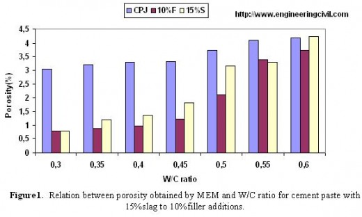
Cement paste: The effect of (w/c) ratio on the porosities of cement paste is shown in Table4. The porosity of hydrated cement based upon methanol exchange as a function of various water cement ratio of different additive content with ages is shown in Fig1.
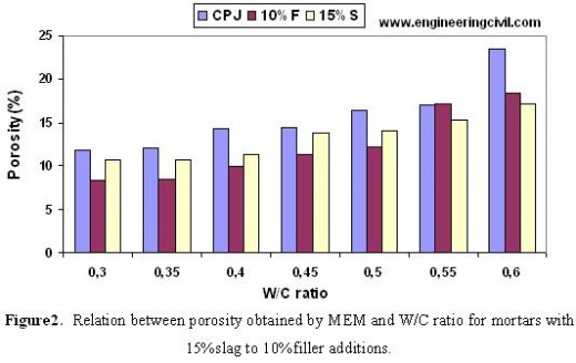
The mortar, The effect between (w/c) ratios and the porosities of mortars is shown in Table5. The porosity of hydrated mortars cements upon methanol exchange as a function of various water cement ratio of different additive content with ages is shown in Fig2.
Table4 Results of The porosity obtained by MEM and W/C ratio for cement paste without additions.
Table5: Relation between porosity and the W/C ratio for mortar without addition
 Based on methanol exchange porosity test results, it can be noticed that.
Firstly: For the cement paste, the porosity with 10% of filler is lower than that with 15% of slag, and by comparing the results obtained we notices that there is an increase in porosity for the cement paste without additions. That clearly shows us the role of the mineral additions in the reduction of porosity.
Secondly: For the mortar, we notices the same preceding results, but with a small change. For porosity of with (w/c ) ratio equals for 0,6 for mortar containing 10% F, and that containing 15% S, porosity decreased for the mortar with 15% S because the existence of a significant portion of silica as constituting matter added (the slag) in addition to the existence of the sand which contains in its turn the same component (silica).
One can conclude the following points:
• Porosity depends on (w/c ) ratio.
• The reduction of porosity depends on the rate of fineness of the added mineral matter and the rate of its pozzolanic effectiveness to limit this phenomenon.
• The mechanical resistance depends on the reduction of porosity.
• The mineral additions do not contribute to form a significant volume of new hydrated products able to reduce the porosity of the mortars even if resistance in compression can be more or less improved by the flexible activity of the additions in the presence of cement.The flexible contribution of the mineral additions thus has structuring role of the connections of the cementing matrix from the mechanical point of view that a role quantitative role on the reduction of porosity [Anissa Bessa and others.2004].
• This study confirms the effect of (w/c) ratio of cement paste and mortar on the porosity obtained by methanol exchange method.
Without forgetting the studies, realized by [Parrott,1981], which confirms only any risk of modification on the level of the microstructure, of the paste of cement and the mortar.
RELATION BETWEEN MECHANICAL RESISTANCE AND W/C RATIO
The effect of W/C ratio on the mechanical resistance (compressive strength) of mortar is shown in Figure3,4 and 5, respectively.
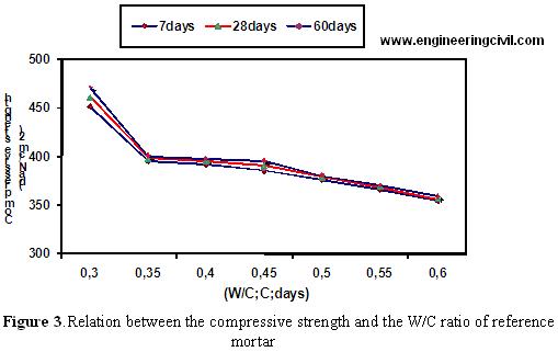
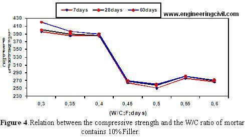
 According to test results, it can be noticed that the mechanical resistance is affected by the water/cement ratio as the mechanical resistance decreases with the increase of water/cement ratio and appreciably the porosity decreases. The increase in cement proportioning and the choice of its type have a favorable influence on the reduction in porosity; the hydrates formed by the hydration of cement have an essential role of filling of the capillaries, and consequently increases the mechanical resistance.
The contribution of the siliceous additions and of the same limestone’s fineness is completely comparable, as well as the absence of a significant chemical effect. Let us note that the fineness supports the physicochemical effect of the additions. Indeed, the presence of a great number of submicron particles in the cementing matrix around the cement grains multiplies the possibilities of germination of the hydrated products and develops micro-structural complexity and the effectiveness of the connections [Anissa Bessa and others.2004].
CONCLUSIONS:
Based on the results of this experimental investigation, the following conclusion can be obtained:
1. The use of mineral additions such as fine slag and calcareous fillers reduces the porosity of cement paste and mortar.
2. Methanol exchange method is a reliable testing method which can be used to obtain the porosity of cement paste and mortar.
3. The increase of water/cement ratio increases the porosity and decreases the compressive strength of cement paste and mortar.
ACKNOWLEDGMENTS
The authors wish to express their gratitude and sincere appreciation to the authority of Port and Airport Research Institute, civil engineering for financing this research work and also several on-going research projects related to Contribution to the mineral addition on the characteristics physiquo-mechanics of the paste of cement and mortar.
REFERENCES
1. Anissa, B., Jean-Philippe. B., and Jean-Louis ,G. ,.” Evaluation of the flexible contribution of additions minerals a porosity, a compressive strength and the durability of the mortars” 22 “èmes university meetings of Civil Engineering, Price Rene Huppert. 2004.
2. Mezghiche, B., A, Boudchicha.” Use of a new approach méthodologique for the evaluation of the effect of additions minerals on the proprieties of the cementing mélanges.
Colloque CMEDIMAT, 06- 07 December, 2005.
3. Lawrence .,P., “on the activity of the fly-ashes and the chemically inert mineral additions in cementing materials “, Thesis of doctorate., INSA of Toulouse ,2000.
4.Parrott, L., J. 1981. “Effect of drying history upon the exchange of pore water with methanol and upon subsequent methanol sorption behavior in hydrated alit paste “ Cement and Concrete Research, Vol .11,p 651 – 658.
We at engineeringcivil.com are grateful to Er.Guimer Tarek for submitting this very useful paper to us. Hope this will help many civil engineers around the world in understanding the impact of adding additional materials on porosity of mortar.
Tel fax: 033 73 45 28
Abstract
This work aims to study the evolution of the resistance of Portland cement pastes and mortars containing two mineral additions such as calcareous filler and finely crushed slag.
The effects of the addition of two mineral additions to Portland cement pastes are mortars, has been carried to evaluate the evolution of the mechanical resistance as function of the age and the mode of the treatment .This study is a simplified approach to show the contribution of the mineral addition on the development of the mechanical resistance, and the porosity obtained using methanol exchange method. In addition, to confirm this study and based on laboratory test resorts approximate equations were obtained
Keywords: Porosities, cement paste, mortar, mechanical resistance, exchange by methanol.
INTRODUCTION
It is widely recognized that the porosity of a material exerts an enormous influences on its physical proprieties. For hardened cement paste a large volume of pores is inherent in the set structure. This porosity is derived mainly from excess water required to ensure cement hydration and provide workability of cement paste, but can also be present due to inadequate compaction. The residue of water filled space in fresh cement paste becomes voids in hardened cement paste. These voids are divided in two classes, capillary pores and gel pores .the former represent the volume of the capillary pores and it depends mainly on both water/ cement ratio of the mix and the degree of hydration. The latter represents the gel pores. As hydration progresses, the amount and distribution of porosity between capillary and gel pores will change. Initially all the pores are capillary pores. As hydration precedes the capillary pore volume is reduced because the capillary space becomes filled with hydration products, and the gel porosity increases. There is a net reduction in total porosity.
During the last fifteen years Mercury intrusion proximity which involve forcing mercury into pores of a body by application of pressure and assuming that all pores have a simple shape, Has been used for determining the pore structures sizes of hydrated cement paste. This method enables a wide range of pore-size distribution to be measured between 1000µm and 30A° depending on the pressure [Orr; 1970]. However, the application of great pressure on hydrated cement paste may cause destruction in the structure and pores below 30A cannot be considered [Shi D and Winslow D N 1985] . In addition to this method there are other investigation involving fluid replacement as methanol and helium pycnometry. The use of methanol as displacement medium for porosity measurement [Scrivener, K L and P l ,1984], have indicated that the porosity values were equivalent to those when helium was used as displacement method. [Parrot, 1981] reported on the effect of drying upon the exchange of pore water with methanol. He found that the water/methanol exchange results of 0.6 water/cement ratio by weight pastes indicated that the pore volume penetration by methanol was only on average 0.7 per cent greater than that occupied by original pore water and the exchange provided reliable pore structure information.
The objective of the current study is to empirically evaluate the participation of physicochemical, microstructures and possibly chemical of the mineral additions on the physical and the mechanical proprieties and the durability of the cement pastes and mortars while being freed from their granular effect. For that a specific experiment al methodology was developed based on the estimation of the impact of the mineral addition built-in in the mixture and to examine their reactivity starting from type of introduced addition and then to measure the total porosity of the mixture (paste / mortar) using methanol to appreciate it. Two mineral addition of different characteristic were introduced to estimate resistance in compression.
Materials
The used cement is a composed Portland cement, produced by cement plant located at AIN-TOUTA , kinds of cement powders were used with Blaine fineness of about 3371 cm2/g (CPJ). The physical properties and chemical analysis of the cement and are listed in Table 1.
The slag powders were used with Blaine fineness of about 3500 cm2/g (Slag S) and 4080 cm2/g (Filler F). The physical properties and chemical analysis of the slag powders and calcareous filler and are listed in Table 2 and 3, respectively.
Table 1: chemical composition of cement
| Chemical Composition (%) | Mineralogical Composition (%) | ||||||||||
| SiO2 | Al2O | Fe2O | CaO | MgO | Free lime | Residue insoluble | Loss on the ignition | C3S | C2S | C3A | C4AF |
| 22,00 | 5,30 | 3,38 | 65,16 | 1,77 | 2,32 | 1,40 | 0,48 | 58,09 | 23,32 | 8,32 | 10,27 |
| Components | SiO2 | Al2 O3 | FeO | CaO | MgO | MnO | S |
| (%) | 40,80 | 5,2 | 0,53 | 43,01 | 6,4 | 3,02 | 0,8 |
Table3 Chemical compositions of the calcareous fillers.
| SiO2 | Fe2O3 | Al2O3 | CaO | MgO | SO3 | NaCl | LOSS ON FIRE |
| 0.58 | 0.02 | 0.06 | 55.80 | 0.06 | 0.08 | 0.56 | 43.53 |
The study was based on the use of a Portland cement made up with the mineral additions of matters such as: the slag (S) and calcareous filler (F) matter separately and with various percentages. The goal considered is on the one hand the evaluation of the rate of participation of these additions and their influence on the mechanical resistance according to time, and of another share the test makes it possible to evaluate existing total porosity in each of the two elements.
1) For the cement paste one used a Portland cement made up (CPJ) of resistance characteristic (42.5 Mpa) for a weight of (20±2) g and a variable (w/c ) ratios between (0.3÷0.6) with the various mineral additions previously quoted.
2) With regard to the mortar, one used the sand of wade with a constant rate of (1350±2) g by preserving same report W/C ratios quoted previously with the change of the quantity of water following the change of report/ratio (w/c)
INVESTIGATION METHODS
The porosity was measured by using the methanol exchange method (MEM).
Methanol exchange:
Determination of the porosity has been achieved by method of solvent replacement. Analar grade methanol was used which can penetrate into the micro-structure without damage. The unbound water in the specimen was replaced by methanol, thus the hydration was arrested and all water eventually replaced by methanol; this is shown by a constant weight of the specimen between 3 and 14days, Specimens were then dried over silica gel for 24 hours at 20 °C. The porosity was measured using methanol exchange [Parrott .1981].
Specimen preparation:
Several small prisms (40*40*160 mm) and cubes 20 mm sides) were cast with water/cement ratios by weight ranged between 0.30and 0.6. Mixing was prolonged and intermitted to minimize bleeding. Careful curing ensured wet conditions for surfaces for the first 24 hours. Following demoulding, samples were kept under wet and dry curing conditions and chosen for test at ages which provided has variation in the porosity. When selected for analysis, cubes were tested in compression. Prisms were cut perpendicular to the longitudinal axis with a diamond saw to yield has 3 mm thick slice. Samples were then immersed immediately in methanol to prevent carbonation and stop hydration prior to the determination of porosity.
Summary of necessary time to produce a sample of hydrated cement paste and mortars are given below, where the limit between brackets time is undertaken for each operation.
• Cutting the sample to yield 3 mm thick slices, (15 mn).
• Drying the sample by methanol exchange, (15 days).
• The samples dryness it stored on silica gel, (15days)
Detail of methanol exchange Method:
The volume of the pores was obtained starting from the weight of the sample saturated superficially dry by methanol minus the dry weight, after having to store the sample in silica gel, divided by the density of methanol.
Vm = (Mss-Ma)/ym
Where
Vm – volume of methanol (cm3)
Mss – mass saturated superficially dry (g)
Ma -The mass dryness (g)
ym – density of methanol (G/cm3)
Pm = Vm/Vt
Pm – porosity by methanol exchange (%)
Vt – total volume (Vt=Vs+Vp)
Vs- the solid volume of a material (cm3)
Vp – the volume of the pores (cm3)
EXPERIMENTAL RESULTS AND DISCUSSION
Cement paste: The effect of (w/c) ratio on the porosities of cement paste is shown in Table4. The porosity of hydrated cement based upon methanol exchange as a function of various water cement ratio of different additive content with ages is shown in Fig1.
The mortar, The effect between (w/c) ratios and the porosities of mortars is shown in Table5. The porosity of hydrated mortars cements upon methanol exchange as a function of various water cement ratio of different additive content with ages is shown in Fig2.
Table4 Results of The porosity obtained by MEM and W/C ratio for cement paste without additions.
| W/C | 0,3 | 0,35 | 0,4 | 0,45 | 0,5 | 0,55 | 0,6 |
| CPJ | 3,04345 | 3,20655 | 3,29655 | 3,31655 | 3,74095 | 4,10139 | 4,19640 |
| 10%F | 0,78957 | 0,87231 | 0,96717 | 1,22612 | 2,10345 | 3,39715 | 3,73607 |
| 15%S | 0,78942 | 1,19732 | 1,35939 | 1,82054 | 3,14370 | 3,29588 | 4,24402 |
| W/C | 0.3 | 0.35 | 0.4 | 0.45 | 0.5 | 0.55 | 0.6 |
| CPJ | 11,7823 | 12,04564 | 14,27554 | 14 ,20532 | 16,37753 | 17,01234 | 25,15748 |
| 10%F | 8,31419 | 8,45825 | 9,94493 | 11,33915 | 12,13005 | 17,25100 | 18,35494 |
| 15%S | 10,69125 | 10,71575 | 11,28004 | 13,74814 | 14,04163 | 15,35882 | 17,22200 |
Firstly: For the cement paste, the porosity with 10% of filler is lower than that with 15% of slag, and by comparing the results obtained we notices that there is an increase in porosity for the cement paste without additions. That clearly shows us the role of the mineral additions in the reduction of porosity.
Secondly: For the mortar, we notices the same preceding results, but with a small change. For porosity of with (w/c ) ratio equals for 0,6 for mortar containing 10% F, and that containing 15% S, porosity decreased for the mortar with 15% S because the existence of a significant portion of silica as constituting matter added (the slag) in addition to the existence of the sand which contains in its turn the same component (silica).
One can conclude the following points:
• Porosity depends on (w/c ) ratio.
• The reduction of porosity depends on the rate of fineness of the added mineral matter and the rate of its pozzolanic effectiveness to limit this phenomenon.
• The mechanical resistance depends on the reduction of porosity.
• The mineral additions do not contribute to form a significant volume of new hydrated products able to reduce the porosity of the mortars even if resistance in compression can be more or less improved by the flexible activity of the additions in the presence of cement.The flexible contribution of the mineral additions thus has structuring role of the connections of the cementing matrix from the mechanical point of view that a role quantitative role on the reduction of porosity [Anissa Bessa and others.2004].
• This study confirms the effect of (w/c) ratio of cement paste and mortar on the porosity obtained by methanol exchange method.
Without forgetting the studies, realized by [Parrott,1981], which confirms only any risk of modification on the level of the microstructure, of the paste of cement and the mortar.
RELATION BETWEEN MECHANICAL RESISTANCE AND W/C RATIO
The effect of W/C ratio on the mechanical resistance (compressive strength) of mortar is shown in Figure3,4 and 5, respectively.
The contribution of the siliceous additions and of the same limestone’s fineness is completely comparable, as well as the absence of a significant chemical effect. Let us note that the fineness supports the physicochemical effect of the additions. Indeed, the presence of a great number of submicron particles in the cementing matrix around the cement grains multiplies the possibilities of germination of the hydrated products and develops micro-structural complexity and the effectiveness of the connections [Anissa Bessa and others.2004].
CONCLUSIONS:
Based on the results of this experimental investigation, the following conclusion can be obtained:
1. The use of mineral additions such as fine slag and calcareous fillers reduces the porosity of cement paste and mortar.
2. Methanol exchange method is a reliable testing method which can be used to obtain the porosity of cement paste and mortar.
3. The increase of water/cement ratio increases the porosity and decreases the compressive strength of cement paste and mortar.
ACKNOWLEDGMENTS
The authors wish to express their gratitude and sincere appreciation to the authority of Port and Airport Research Institute, civil engineering for financing this research work and also several on-going research projects related to Contribution to the mineral addition on the characteristics physiquo-mechanics of the paste of cement and mortar.
REFERENCES
1. Anissa, B., Jean-Philippe. B., and Jean-Louis ,G. ,.” Evaluation of the flexible contribution of additions minerals a porosity, a compressive strength and the durability of the mortars” 22 “èmes university meetings of Civil Engineering, Price Rene Huppert. 2004.
2. Mezghiche, B., A, Boudchicha.” Use of a new approach méthodologique for the evaluation of the effect of additions minerals on the proprieties of the cementing mélanges.
Colloque CMEDIMAT, 06- 07 December, 2005.
3. Lawrence .,P., “on the activity of the fly-ashes and the chemically inert mineral additions in cementing materials “, Thesis of doctorate., INSA of Toulouse ,2000.
4.Parrott, L., J. 1981. “Effect of drying history upon the exchange of pore water with methanol and upon subsequent methanol sorption behavior in hydrated alit paste “ Cement and Concrete Research, Vol .11,p 651 – 658.
We at engineeringcivil.com are grateful to Er.Guimer Tarek for submitting this very useful paper to us. Hope this will help many civil engineers around the world in understanding the impact of adding additional materials on porosity of mortar.
In which direction should the main weight of reinforcement be placed in concrete pavement?
The reinforcement of concrete pavement is usually in the form of long mesh type. A road usually has length is generally much longer than its width and therefore cracking in the transverse direction has to be catered
for in design. Reinforcement is required in the longitudinal direction to limit transverse cracking while transverse steel acts to provide rigidity to support the mesh fabrics. For long mesh in concrete slab, the main weight of reinforcement should be placed in the critical direction (i.e. longitudinal direction) to control cracking. However, if the concrete road is quite wide, certain reinforcement has to be placed in the transverse direction in this
case to control longitudinal cracking.
This question is taken from book named – A Self Learning Manual – Mastering Different Fields of Civil Engineering Works (VC-Q-A-Method) by Vincent T. H. CHU.
What is Marshall Mix Design for Bituminous Materials?
The Marshall Mix Design method was originally developed by Bruce Marshall of the Mississippi Highway Department in 1939. The main idea of the Marshall Mix Design method involves the selection of the asphalt binder content with a suitable density which satisfies minimum stability and range of flow values.
The Marshall Mix Design method consists mainly of the following steps:
(i) Determination of physical properties, size and gradation of aggregates.
(ii) Selection of types of asphalt binder.
(iii) Prepare initial samples, each with different asphalt binder content.
For example, three samples are made each at 4.5, 5.0, 5.5, 6.0 and 6.5 percent asphalt by dry weight for a total of 15 samples. There should be at least two samples above and two below the estimated optimum asphalt content.
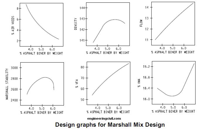
(iv) Plot the following graphs:
(vi) Determine properties at this optimum asphalt binder content by reference with the graphs. Compare each of these values against design requirements and if all comply with design requirements, then the selected optimum asphalt binder content is acceptable. Otherwise, the mixture should be redesigned.
 This question is taken from book named – A Self Learning Manual – Mastering Different Fields of Civil Engineering Works (VC-Q-A-Method) by Vincent T. H. CHU.
The Marshall Mix Design method consists mainly of the following steps:
(i) Determination of physical properties, size and gradation of aggregates.
(ii) Selection of types of asphalt binder.
(iii) Prepare initial samples, each with different asphalt binder content.
For example, three samples are made each at 4.5, 5.0, 5.5, 6.0 and 6.5 percent asphalt by dry weight for a total of 15 samples. There should be at least two samples above and two below the estimated optimum asphalt content.
(iv) Plot the following graphs:
(a) Asphalt binder content vs. density
(b) Asphalt binder content vs. Marshall stability
(c) Asphalt binder content vs. flow
(d) Asphalt binder content vs. air voids
(e) Asphalt binder content vs. voids in mineral aggregates
(f) Asphalt binder content vs voids filled with asphalt
(v) Determine the asphalt binder content which corresponds to the air void content of 4 percent(b) Asphalt binder content vs. Marshall stability
(c) Asphalt binder content vs. flow
(d) Asphalt binder content vs. air voids
(e) Asphalt binder content vs. voids in mineral aggregates
(f) Asphalt binder content vs voids filled with asphalt
(vi) Determine properties at this optimum asphalt binder content by reference with the graphs. Compare each of these values against design requirements and if all comply with design requirements, then the selected optimum asphalt binder content is acceptable. Otherwise, the mixture should be redesigned.
What is the principle of Asphalt Mix Design?
The main objective of asphalt mix design is to achieve a mix with economical blending of aggregates with asphalt to achieve the following :
(i) workability to facilitate easy placement of bituminous materials without experiencing segregation;
(ii) sufficient stability so that under traffic loads the pavement will not undergo distortion and displacement;
(iii) durability by having sufficient asphalt;
(iv) sufficient air voids
In asphalt mix design, high durability is usually obtained at the expense of low stability. Hence, a balance has to be stricken between the durability and stability requirements.
Economics of R.C.C. Water tank Resting over Firm Ground vis-a-vis Pre-stressed Concrete Water Tank Resting over Firm Ground
By
MS. SNEHAL R. METKAR
(P.G. STUDENT)
DEPARTMENT OF CIVIL ENGINEERING
(STRUCTURAL ENGINEERING IIND YEAR)
P.R.M.T OF TECH. & RESEARCH, BADNERA-AMRAVATI
SANT. GADGE BABA (AMARAVATI) UNIVERSITY (MAHARASHTRA)
COUNTRY INDIA – 444701
GUIDED BY
Prof A. R. Mundhada
(PROFESSOR)
DEPARTMENT OF CIVIL ENGINEERING,
P.R M.I.T.R., BADNERA, AMRAVATI.
MAHARASHTRA, INDIA-4444701,
Abstract
Water tanks are used to store water and are designed as crack free structures, to eliminate any leakage. In this paper design of two types of circular water tank resting on ground is presented. Both reinforced concrete (RC) and prestressed concrete (PSC) alternatives are considered in the design and are compared considering the total cost of the tank. These water tank are subjected to the same type of capacity and dimensions. As an objective function with the properties of tank that are tank capacity, width &length etc.
A computer program has been developed for solving numerical examples using the Indian std. Indian Standard Code 456-2000, IS-3370-I,II,III,IV & IS 1343-1980. The paper gives idea for safe design with minimum cost of the tank and give the designer the relationship curve between design variable thus design of tank can be more economical ,reliable and simple. The paper helps in understanding the design philosophy for the safe and economical design of water tank.
Keywords
Rigid based water tank, RCC water tank, Prestressed Concrete, design, details, minimum total cost, tank capacity
I. INTRODUCTION
Storage reservoirs and over head tanks are used to store water, liquid petroleum, petroleum products and similar liquids. The force analysis of the reservoirs or tanks is about the same irrespective of the chemical nature of the product. In general there are three kinds of water tanks-tanks resting on ground Underground tanks and elevated tanks. Here we are studying only the tanks resting on ground like clear water reservoirs, settling tanks, aeration tanks etc. are supported on ground directly. The wall of these tanks are subjected to pressure and the base is subjected to weight of Water.
In this paper, both types of reinforced concrete and prestesses concrete water tanks resting on ground monolithic with the base Are design and their results compared. These tanks are subjected to Same capacity and dimensions. Also a computer program has been developed for solving numerical examples using IS Code 456-200IS-1343-1984,IS 3370-Part I,II,III,IV 1965 & IS Code 1343-1980. From the analysis it is conclude that for tank having larger capacity (greater than 10 lakh liter) prestesses concrete water tank is economical.
Objective
• To make the study about the analysis and design of water tank.
• To make the guidelines for the design of liquid retaining structure According to IS code.
• To know about design philosophy for safe design of water tank.
• To develop program for water tank to avoid tedious calculations.
• To know economical design of water
• This report is to provide guidance in the design and construction of circular priestesses concrete using tendons
Previous Research
From the review of earlier investigations it is found that considerable work has been done on the method of analysis and design of water tanks.
Tanetal. [1]:- (1993) presented the minimum cost design of reinforced concrete cylindrical water tanks based on the British Code for water tanks, using a direct search method and the (SUMT). The cost function included the material costs of concrete and steel only. The tank wall thickness was idealized with piecewise linear slopes with the maximum thickness at the base.
Thakkar and Sridhar Rao [2] (1974), discussed cost optimization of non cylindrical composite type prestressed concrete pipes based on the Indian code.
Al-Badri [3] (2005) presented cost optimization of reinforced concrete circular grain silo based on the ACI Code (2002). He proved that the minimum cost of the silo increases with increasing of the angle of internal friction between stored materials, the coefficient of friction between stored materials and concrete, and the number of columns supporting hopper . Al-Badri (2006) presented the minimum cost design of reinforced concrete corbels based on AC I Code (2002). The cost function included the material costs of concrete, formwork and steel reinforcement. He proved that the minimum total cost of the corbel increases with the increase of the shear span, and decreases with the increase of the friction factor for monolithic construction.
Hassan Jasim Mohammed [4] studied the economical design of concrete water Tanks by optimization method. He applied the optimization technique to the structural design of concrete rectangular and circular water tank, considering the total cost of the tank as an objective function with the properties of the tank viz. tank capacity, width and length of the tank, unit weight of water and tank floor slab thickness as design variables. From the study he concluded that an increased tank capacity leads to increased minimum total cost of the rectangular tank but decreased minimum total cost for the circular tank. The tank floor slab thickness constitutes the minimum total cost for two types of tanks. The minimum cost is more sensitive to changes in tank capacity and floor slab thickness of rectangular tank but in circular type is more sensitive to change in all variables. Increased tank capacity leads to increase in minimum total cost. Increase in water depth in circular tank leads to increase in minimum total cost.
Abdul-Aziz & A. Rashed [5] rationalized the design procedure for reinforced and prestressed concrete tanks so that an applicable Canadian design standard could be developed. The study investigates the concept of partial prestressing in liquid containing structures. The paper also includes experimental and analytical phases of total of eight full scale specimens, representing segments from typical tank walls, subjected to load and leakage tests. In analytical study a computer model that can predict the response of tank wall segments is described and calibrated against the test results. The proposed design procedure addresses the leakage limit state directly. It is applicable for fully prestressed, fully reinforced and partially prestressed concrete water tanks. The conclusions that are drawn are as follows:-
• A design method based on limiting the steel stress, does not produce consistent crack or compression zone depths under the application of prestressing nor under a combination of axial load and moment.
• A design method based on providing a residual compressive stress in concrete dose not utilizes non-prestressed reinforcement effectively.
• Relaxing the residual compressive stress requirement permits a more efficient design. The stresses in non-prestresssed steel are higher, but remain below yield under service load. Therefore, less reinforcement is required.
• Load eccentricity significantly affects the behavior of the prestressed concrete sections. The behavior with a small load eccentricity, less than about half the thickness, the section may be treated as a flexure member.
• The ratio of non prestressed steel to prestressed steel in partially prestressed concrete section has a significant effect on the member serviceability and strength. Choosing the ratio such that both non-prestress and prestressed steel reach their strength simultaneously utilizes both types of steel at the ultimate limit state effectively.
• Increasing the wall thickness is very effective in increasing the capacity of the section and improving its serviceability by increasing the compression zone depth and reducing the deformations.
Chetan Kumar Gautam [6] Highlights the point named “Comparison of Circular Reinforced Concrete and Prestressed Concrete Underground Shelter”. In his paper, design of two types of large circular underground shelters is presented. The shelters are made of precast concrete sections. Both RC and PSC alternatives are considered in the design and compared. The shelters are subjected to same type of external loadings and support conditions. The study conclude that the feasibility of using the vertical casting process of making the modules of shelters as it is suitable for manufacturing of large diameter pipes. He also suggested that the incorporation of fibers, specially steel fibers improves a host of properties of concrete, including its crack resistance, flexural strength, ductility, etc. Thus, the possibility of incorporating fibers in concrete shelter may be explored.
II DESIGN PHILOSOPHY
For R.C.C. water tank
For Prestresed Concrete water tank
For R.C.C Structure
Permissible stresses in concrete
• For resistance to cracking:-
Design of liquid retaining structure is different from R.C.C. structures. As it requires that concrete should not crack and hence tensile stresses in concrete should be within permissible limit.(i.e. TYPE-I structure).A reinforced concrete member of liquid retaining structure is design on the usual principle ignoring tensile resistance of concrete in bending. accordingly it should be ensure that tensile stresses on the liquid retaining face of the equivalent concrete section dose not exceed the permissible tensile strength of concrete as given in table1.
Table 1(Permissible Compressive Stresses In Calculations Relating To Resistance To Cracking)
• For strength calculation
In strength calculations the permissible Concrete stresses shall be in accordance with Table1. Where the calculated shear stress in concrete a lone exceeds the permissible value, reinforcement acting in conjunction with diagonal compression in the concrete shall be provided to take the whole of the shear.
Permissible Stresses In Steel
• For resistance to cracking.
When steel and concrete are assumed to act together for checking the tensile stress in concrete for avoidance of crack, the tensile stress in steel as in table 2will be limited by the requirement that the permissible tensile stress in the concrete is not exceeded so the tensile stress in steel shall be equal to the product of modular ratio of steel and concrete, and the corresponding allowable tensile stress in concrete.
• For strength calculations
In strength calculations the permissible stress shall be as given in table 2.
Table 2 (Permissible Stresses In Steel Reinforcement For Strength Calculation)
Design Requirement
Generally M30 grade of concrete should be used Design Mix (1:1*1/2:3)Steel reinforcement should not less than0.3% of the gross section shall be provided in each direction Floors:-floor may be constructed of concrete with nominal % of reinforcement smaller than provided in table 1.they are cast in panels with sides not more than 45m and with contraction or expansion joints in between..In such cases a screed or concrete layer(M10) not less than 75mm thick shall placed first on the ground and covered with a sliding layer of bitumen paper to destroy the bond between the screed and the floor.
Minimum Cover:- 35mm(both the faces).
Minimum Reinforcement:-Overall .24% of total cross section should be provided.
Walls:-1) provision of joints
( a ) Where it is desired to allow the walls to expand or contract separately from the floor , or to prevent moments at the base of the wall owing to fixity to the floor sliding joints may be employed.
( b) The spacing of vertical movement joints should be as discussed. while the majority of these joints may be of the partial or complete contraction type , sufficient joints of the expansion type should be provided to satisfy the requirements given in article.
2)Pressure on wall
(a) In liquid retaining structures with fixed or floating covers the gas pressure developed above liquid surface shall be added to the liquid pressure .
(b)When the wall of liquid retaining structure is built in ground, or has earth embanked against it ,the effect of earth pressure shall be taken in to account .
III Design stepes:
• Calculate diameter and height of water tank
• Assumed suitable thickness
• Calculate designed constants
• Calculate hoop tension, maximum bending moment by using IS 1370 part IV.
• Calculate hoop steel(provide in the form of rings per meter height)
• Check the assume thickness with given permissible values of tensile stresses of concrete in direct tension for the given grade of concrete.
• Check of thickness for bending
• Provide vertical steel
• Design base slab
• Draw details
Introduction of compressive stresses to a structural member with high-strength steel that counteract the tensile stresses resulting from applied loads
Prestressed Concrete
Pre-Tensioned (cast off-site in beds- precast members)
Post-Tensioned (cast on-site in place)
All types of structure can be built with reinforced and pre-stressed concrete: columns, piers, walls, slabs, beams, arches, frames, even suspended structures and of course shells and folded plates.
• Tanks
• Foundation panels
• Poles
• Modular block retaining wall system
• Wall panels
• Concrete units
• Slabs
• Roofing and flooring
• Lintel and sunshade
• Beams
• Columns girders
Tanks:-
In the construction of concrete structures for the storage of liquids, the imperviousness of concrete is an important basic requirement. Hence, the design of such construction is based on avoidance of cracking in the concrete. The structures are prestressed to avoid tension in the concrete. In addition, prestressed concrete tanks require low maintenance. The resistance to seismic forces is also satisfactory. Prestressed concrete tanks are used in water treatment and distribution systems, waste water collection and treatment system and storm water management. Other applications are liquefied natural gas (LNG) containment structures, large industrial process tanks and bulk storage tanks. Strand Wrapped circular pre-stressed concrete tanks are long life liquid storage structure with virtually no maintenance. Concrete construction makes for a substantial, sturdy tank structure that easily contain the internal liquid pressure while comfortably resisting external forces such as earthquake, wind.
Pre-stressed concrete is the most efficient material for water tanks and coupled with the circular shape, eliminates all stress conditions. By placing the steel of the pre-stressed strands in tension and the concrete in compression, both materials are in an ideal states and the loads are uniformly distributed around the tank circumference.
Properties
1) Low maintenance can be enjoyed throughout the life as these are built with concrete, durable material that never corrodes and does not require coatings when in contact with water or the environment.
2) Pre-stressing counteracts the differential temperature and dryness loads that a tank core wall experience. The tank walls are wet on the inside and dry on outside and the temperature varies between the two sides. If not properly accounted for, these moisture and temperature differential will cause a tank wall to bend and crack. Counteract these force in both the vertical and horizontal direction and diminish subsequently the cracking and leaking
3) Tanks are very ductile, enabling to withstand seismic forces and varying water backfill.
4) Tanks utilize material efficiently – steel in tension, concrete in compression
5) Pre-cast tanks can store or treat anything from potable water to hazardous waste to solid storage bins.
6)Storage capacities can range from 0.4 to 120 mega liters
7) Diameters of the tank can vary up to 90 m
V Design philosophy
A. Loads: Circumferential prestressing also typically causes vertical bending moment from other loading condition.
B. Freeboard: freeboard should be provided in the tank wals to minimize earthquake- induced hydrodynamic effects on a flat roof.
C. Wall: The design of the wall should be based on elastic cylindrical shell analysis, considering the effects of prestressing, internal loads and other external loads.cast in place concrete walls is usually priestesses circumferentially with high-strength strand tendons placed in ducts in the wall .the wall may be priestesses with bonded and unbounded tendons. Vertical prestessed reinforcement near the center of the wall thickness, or vertical non prestessed reinforcement near each face, may be used. Non priestesses reinforcement may be provided vertically in conjunction with vertical prestressing.
Precast concrete walls usually consist of precast panels curved to the tank radius with joints between panels filled with high-strength concrete. the panels are post-tensioned circumferentially by high strength strand tendons. the tendons maybe embedded within the precast panels or placed on the external surface of the wall and protected by shortcreat .the wall panels may be prestessesd vertically with pretensioned strands or post-tensioned tendons.non prestesses reinforcement may be provided vertically with or without vertical prestressing.
 Construction Methodology
The construction of the tanks is in the following sequence. First, the concrete core is cast and cured. The surface is prepared by sand or hydro blasting. Next, the circumferential prestressing is applied by strand wrapping machine. Shotcrete is applied to provide a coat of concrete over the prestressing strands. A few photographs are provided for illustration.
IS: 3370 (Code of Practice for Concrete Structures for the Storage of Liquids) provides guidelines for the analysis and design of liquid storage tanks. The four sections of the code are titled as follows.
Part 1: General Requirement
Part 2: Reinforced Concrete Structures
Part 3: Prestressed Concrete Structures
Part 4: Design Tables
The following types of boundary conditions are considered in the analysis of the cylindrical wall.
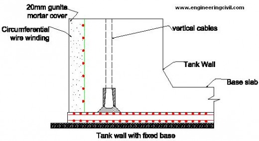
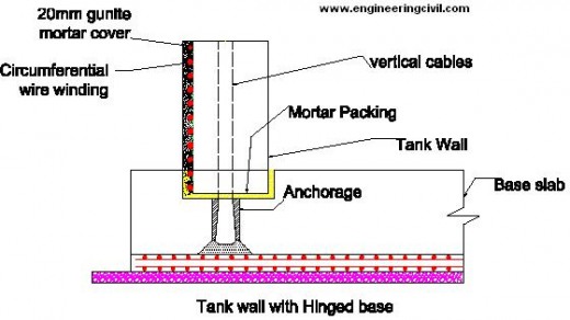
a) For base: fixed or hinged
b) For top: free or hinged or framed.
1)For base
Fixed: When the wall is built continuous with its footing, then the base can be considered to be fixed as the first approximation.
 Hinged: If the sub grade is susceptible to settlement, then a hinged base is a conservative assumption. Since the actual rotational restraint from the footing is somewhere in between fixed and hinged, a hinged base can be assumed. The base can be made sliding with appropriate polyvinyl chloride (PVC) water-stops for liquid tightness.
 2) For top
Free: The top of the wall is considered free when there is no restraint in expansion.
Hinged: When the top is connected to the roof slab by dowels for shear transfer, the boundary condition is considered to be hinged.
The hydrostatic pressure on the wall increases linearly from the top to the bottom of the liquid of maximum possible depth. If the vapour pressure in the free board is negligible, then the pressure at the top is zero. Else, it is added to the pressure of the liquid throughout the depth. The forces generated in the tank due to circumferential prestress are opposite in nature to that due to hydrostatic pressure. If the tank is built underground, then the earth pressure needs to be considered.
The hoop tension in the wall, generated due to a triangular hydrostatic pressure is given as T = CTw H Ri
The bending moment in the vertical direction is given as
M = CMwH3
The shear at the base is given by the expression V = CVw H
Where,
CT = coefficient for hoop tension
CM = coefficient for bending moment
CV = coefficient for shear
w = unit weight of liquid
H = height of the liquid
Ri = inner radius of the wall.
The values of the coefficients are tabulated in IS:3370 – 1967, Part 4, for various values of H2/Dt, at different depths of the liquid. D and t represent the inner diameter and the thickness of the wall, respectively. The typical variations of CT and CM with depth, for two sets of boundary conditions are illustrated. The roof can be made of a dome supported at the edges on the cylindrical wall. Else, the roof can be a flat slab supported on columns along with the edges. IS:3370 – 1967, Part 4, provides coefficients for the analysis of the floor and roof slabs.
 Design steps
• Calculate diameter and height of water tank
• Assumed suitable thickness
• Calculate designed constants
• Calculate hoop tension, maximum bending moment by using IS 1370 part IV.
• Check the assume thickness with given permissible values of tensile stresses of concrete in direct tension for the given grade of concrete.
• Actual circumferential prestress i.e. actual direct compressive stress (fc)
• Provide circumferential steel , Provide vertical steel
• Check for ultimate collapse and cracking
• Non prestressing steel /untensioned steel
• Design base slab
• Draw detail
 Comparison of R.C.C. water tank and Prestrssed water tank
The tanks to be consider having some common data such as the tanks are having same capacity, same diameter, same height, same grade of concrete i. e. (M40) & (M50), the thickness of tank floor should be taken either 150mm or equal to the wall thickness(if greater than 150mm) for RCC water tank and minimum thickness for priestesses concrete water tank is 120mm.We consider tank capacity for both the cases (i.e. RCC & Priestesses) reimaging from 1000 m3 to 9000 m3. for both the grade of concrete i.e. (M40 & M50). The result so obtained as given in following table3
NOTE: (Negative value of % saving indicates that prestressed concrete tank is economical than RCC water tank and vice-à-versa)
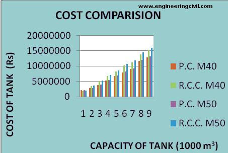 Figure 1: Variation Of Cost With Capacity Of Water Tank & Grade Of Concrete
 Figure 2 Variation Of Cost For Both Type Of Water Tank With Same Grade Of Concrete(M40)
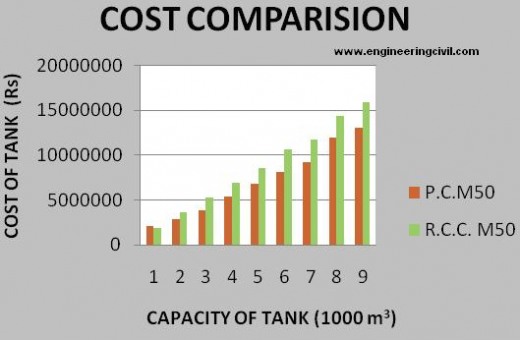 Figure 3 Variation Of Cost For Both Type Of Water Tank With Same Grade Of Concrete(M50)
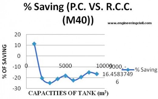 Figure 4 Variation of % of saving for given capacity with given grade of concrete(M40)
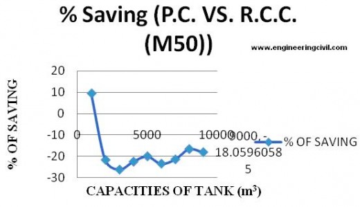 Figure 5 Variation of % of saving for given capacity with given grade of concrete(M50)
The aim of this paper is to compare the cost of R.C.C. water tanks resting over firm ground with the cost of Prestressed concrete water tanks. In India at least, most of the small & medium sized water tanks are constructed in RCC. Senior engineers and those in the know maintain that prestressed concrete water tanks are not worth trying for smaller capacities. Besides cost, other reason may be that prestressed concrete construction involves skilled labor & supervision. Furthermore, prestressing is a closely guarded technology in this country & information is not available that easily.
There is no clear-cut definition of “Medium Size”. The thumb rule passed on in the field from one generation of engineers to the next, fixes a value around 10 lac liters. Therefore, this study encompasses tanks from 10 lac liter capacity to 90 lac liter capacity. A couple of cases of both varieties were designed manually. Design & Estimation programs were developed in MS EXCEL for both RCC & Prestressed concrete. The programs were finalized after a number of trial runs & corrections.
Results obtained are compiled in figures numbered 1 to 5 & Table numbered 3. D/H ratio for all the tanks is maintained at 4 based on the recommendations of the Preload Engineering Company of the US, a world leader in the field of prestressed concrete water tanks. It should be noted that an increase in tank wall thickness results in decreased flexural steel in case of RCC. However, in case of prestressed concrete, an increased thickness leads to a greater prestressing force & consequently more prestressing steel. Thus, increased thickness leads to increased cost in case of prestressed concrete.
Table3 presents the total cost of each tank along with the % difference. “+” means costlier prestressing & “-“ means cheaper prestressing. As the tank capacity increases, the cost of tank increases. But the concept of “economics of scale” holds good i.e. the cost of a tank of 20 lac liter capacity is less than double the cost of a tank of 10 lac liter capacity. Similarly, the cost of a tank of 90 lac liter capacity is less than 9 times the cost of a tank of 10 lac liter capacity. It can be clearly established that the grade of concrete hardly makes any difference in the costing. Because of its nature, the water tank design is never an impending or boundary line design. The factor of safety is high & the actual stresses are much lower than the permissible ones. An increased permissible stress for a higher grade of concrete hardly makes any difference to the final outcome.
Finally, a study of the same Table3 confirms that the RCC tank is cheaper only for 10 lac liter capacity. For higher capacities, prestress concrete tank is always cheaper by @ (20 +/- 5) %. This is because the thickness of an RCC tank increases many-folds for higher capacities. Thickness in fact seems to be an important criterion even for prestressed tanks. An increased thickness leads to an increased prestressing force. More steel is required to generate this higher prestressing force resulting in higher cost.
CONCLUSION
RCC tanks are cheaper only for smaller capacities up to 10-12 lac liters. For bigger tanks, Prestressing is the superior choice resulting in a saving of @ 20%.
REFERENCES:
1 Tanetal (1966) “Minimum Cost Design Of Reinforced Concrete Cylindrical Water Tanks Based On The British Code For Water Tanks, Using A Direct Search Method And The (SUMT). European Journal Of Scientific Research ISSN 1450 -216XVol.49No.4(2011),pp.510-520.
2 Thakkar and Sridhar Rao (1974)”Cost Optimization Of Cylindrical Composite Type Prestesses Concrete Pipes Based On The Indian Code” Journal of Structural Engineering 131: 6.
3 Al-Badri (2005) “Cost Optimization Of Reinforced Concrete Circular Grain Silo Based On ACI Code (2002)American Concrete Institute Structural Journal, May- June 2006.
4 Hassan Jasim Mohammed “ Economical Design Of Water Tanks” European Journal Of Scientific Research ISSN 1450 -216XVol.49No.4(2011),pp.510-520.
5 Abdul-Aziz & A. Rashed “Rational Design Of Priestesses And Reinforced Concrete Tanks” Dept Of Civil & Environmental Engineering. University Of Alberta, Edmontan, Alberta Canada T6g-267.Eurojournals Publishing. Inc.2011
6 Chetan Kumar Gautam “Comparison Of Circular RC And PSC Underground Shelters” The Indian Concrete Journal April 2006.
7 Precon “Designing Of Circular Prestressed Concrete Tanks To The Industry Standards Of The AWWA And ACI” journal of priestesses concrete institute vol.12,apr. 1967
8 IS: 456-2000. Indian Standard Code of Practice For Reinforced Concrete.
9 IS 3370-Part I,II,III,IV 1965 & IS Code 1343-1980 Indian Standard Code of Practice For Liquid Retaining Structures.
10 IS: 1343- 1980. Indian Standard Code of Practice For Prestressed Concrete (First Revision).
11 Lin, T.Y, and NED H BURNS “Prestressed Concrete”, Third Edition , John Wiley & Sons[ ASIA] Pt e Ltd. , Singapore 129809.
12 N. Krishna Raju, 2007. “Prestressed Concrete”, Fourth Edition, Tata McGraw- Hill Company Ltd., New Delhi.
13 A.K Jain Reinforced concrete (vol-1,vol-2)
14 B.N Dutta, 2009 “Estimating and Costing In Civil Engineering”, Twenty- Sixth Revised Edition UBS Publishers’ Distributors Pvt. Ltd. New Delhi.
15 Current Schedule of Rates (CSR), 2010-2011, for Public Works Region, Amravati.
16 Schedule Of Rates Year 2010-2011, For Maharashtra Jeevan Pradhikaran, Nagpur Region
17 Bundy , B. D. , 1984. ” Basic Optimization Methods “, Edward Arnold Publishers.
18 Fintel, M., ,1974. ” Handbook of Concrete Engineering”, USA.
19 Gray ,W.S. and Manning ,G.P., 1960. ” Concrete Water Tower, Bunkers, Silos and Other Elevated Structures” , 3rd ed. , London.
20 Manning, G.P., 1973. ” Reinforced Concrete Reservoirs and Tanks,1st ed. London.
We at engineeringcivil.com are thankful to MS. SNEHAL R. METKAR for submitting this useful information to us. We hope this will be of great help to all those who are looking forward for Economics of R.C.C. Water tank Resting over Firm Ground vis-a-vis Pre-stressed Concrete Water Tank Resting over Firm Ground.
MS. SNEHAL R. METKAR
(P.G. STUDENT)
DEPARTMENT OF CIVIL ENGINEERING
(STRUCTURAL ENGINEERING IIND YEAR)
P.R.M.T OF TECH. & RESEARCH, BADNERA-AMRAVATI
SANT. GADGE BABA (AMARAVATI) UNIVERSITY (MAHARASHTRA)
COUNTRY INDIA – 444701
GUIDED BY
Prof A. R. Mundhada
(PROFESSOR)
DEPARTMENT OF CIVIL ENGINEERING,
P.R M.I.T.R., BADNERA, AMRAVATI.
MAHARASHTRA, INDIA-4444701,
Abstract
Water tanks are used to store water and are designed as crack free structures, to eliminate any leakage. In this paper design of two types of circular water tank resting on ground is presented. Both reinforced concrete (RC) and prestressed concrete (PSC) alternatives are considered in the design and are compared considering the total cost of the tank. These water tank are subjected to the same type of capacity and dimensions. As an objective function with the properties of tank that are tank capacity, width &length etc.
A computer program has been developed for solving numerical examples using the Indian std. Indian Standard Code 456-2000, IS-3370-I,II,III,IV & IS 1343-1980. The paper gives idea for safe design with minimum cost of the tank and give the designer the relationship curve between design variable thus design of tank can be more economical ,reliable and simple. The paper helps in understanding the design philosophy for the safe and economical design of water tank.
Keywords
Rigid based water tank, RCC water tank, Prestressed Concrete, design, details, minimum total cost, tank capacity
I. INTRODUCTION
Storage reservoirs and over head tanks are used to store water, liquid petroleum, petroleum products and similar liquids. The force analysis of the reservoirs or tanks is about the same irrespective of the chemical nature of the product. In general there are three kinds of water tanks-tanks resting on ground Underground tanks and elevated tanks. Here we are studying only the tanks resting on ground like clear water reservoirs, settling tanks, aeration tanks etc. are supported on ground directly. The wall of these tanks are subjected to pressure and the base is subjected to weight of Water.
In this paper, both types of reinforced concrete and prestesses concrete water tanks resting on ground monolithic with the base Are design and their results compared. These tanks are subjected to Same capacity and dimensions. Also a computer program has been developed for solving numerical examples using IS Code 456-200IS-1343-1984,IS 3370-Part I,II,III,IV 1965 & IS Code 1343-1980. From the analysis it is conclude that for tank having larger capacity (greater than 10 lakh liter) prestesses concrete water tank is economical.
Objective
• To make the study about the analysis and design of water tank.
• To make the guidelines for the design of liquid retaining structure According to IS code.
• To know about design philosophy for safe design of water tank.
• To develop program for water tank to avoid tedious calculations.
• To know economical design of water
• This report is to provide guidance in the design and construction of circular priestesses concrete using tendons
Previous Research
From the review of earlier investigations it is found that considerable work has been done on the method of analysis and design of water tanks.
Tanetal. [1]:- (1993) presented the minimum cost design of reinforced concrete cylindrical water tanks based on the British Code for water tanks, using a direct search method and the (SUMT). The cost function included the material costs of concrete and steel only. The tank wall thickness was idealized with piecewise linear slopes with the maximum thickness at the base.
Thakkar and Sridhar Rao [2] (1974), discussed cost optimization of non cylindrical composite type prestressed concrete pipes based on the Indian code.
Al-Badri [3] (2005) presented cost optimization of reinforced concrete circular grain silo based on the ACI Code (2002). He proved that the minimum cost of the silo increases with increasing of the angle of internal friction between stored materials, the coefficient of friction between stored materials and concrete, and the number of columns supporting hopper . Al-Badri (2006) presented the minimum cost design of reinforced concrete corbels based on AC I Code (2002). The cost function included the material costs of concrete, formwork and steel reinforcement. He proved that the minimum total cost of the corbel increases with the increase of the shear span, and decreases with the increase of the friction factor for monolithic construction.
Hassan Jasim Mohammed [4] studied the economical design of concrete water Tanks by optimization method. He applied the optimization technique to the structural design of concrete rectangular and circular water tank, considering the total cost of the tank as an objective function with the properties of the tank viz. tank capacity, width and length of the tank, unit weight of water and tank floor slab thickness as design variables. From the study he concluded that an increased tank capacity leads to increased minimum total cost of the rectangular tank but decreased minimum total cost for the circular tank. The tank floor slab thickness constitutes the minimum total cost for two types of tanks. The minimum cost is more sensitive to changes in tank capacity and floor slab thickness of rectangular tank but in circular type is more sensitive to change in all variables. Increased tank capacity leads to increase in minimum total cost. Increase in water depth in circular tank leads to increase in minimum total cost.
Abdul-Aziz & A. Rashed [5] rationalized the design procedure for reinforced and prestressed concrete tanks so that an applicable Canadian design standard could be developed. The study investigates the concept of partial prestressing in liquid containing structures. The paper also includes experimental and analytical phases of total of eight full scale specimens, representing segments from typical tank walls, subjected to load and leakage tests. In analytical study a computer model that can predict the response of tank wall segments is described and calibrated against the test results. The proposed design procedure addresses the leakage limit state directly. It is applicable for fully prestressed, fully reinforced and partially prestressed concrete water tanks. The conclusions that are drawn are as follows:-
• A design method based on limiting the steel stress, does not produce consistent crack or compression zone depths under the application of prestressing nor under a combination of axial load and moment.
• A design method based on providing a residual compressive stress in concrete dose not utilizes non-prestressed reinforcement effectively.
• Relaxing the residual compressive stress requirement permits a more efficient design. The stresses in non-prestresssed steel are higher, but remain below yield under service load. Therefore, less reinforcement is required.
• Load eccentricity significantly affects the behavior of the prestressed concrete sections. The behavior with a small load eccentricity, less than about half the thickness, the section may be treated as a flexure member.
• The ratio of non prestressed steel to prestressed steel in partially prestressed concrete section has a significant effect on the member serviceability and strength. Choosing the ratio such that both non-prestress and prestressed steel reach their strength simultaneously utilizes both types of steel at the ultimate limit state effectively.
• Increasing the wall thickness is very effective in increasing the capacity of the section and improving its serviceability by increasing the compression zone depth and reducing the deformations.
Chetan Kumar Gautam [6] Highlights the point named “Comparison of Circular Reinforced Concrete and Prestressed Concrete Underground Shelter”. In his paper, design of two types of large circular underground shelters is presented. The shelters are made of precast concrete sections. Both RC and PSC alternatives are considered in the design and compared. The shelters are subjected to same type of external loadings and support conditions. The study conclude that the feasibility of using the vertical casting process of making the modules of shelters as it is suitable for manufacturing of large diameter pipes. He also suggested that the incorporation of fibers, specially steel fibers improves a host of properties of concrete, including its crack resistance, flexural strength, ductility, etc. Thus, the possibility of incorporating fibers in concrete shelter may be explored.
II DESIGN PHILOSOPHY
For R.C.C. water tank
For Prestresed Concrete water tank
For R.C.C Structure
Permissible stresses in concrete
• For resistance to cracking:-
Design of liquid retaining structure is different from R.C.C. structures. As it requires that concrete should not crack and hence tensile stresses in concrete should be within permissible limit.(i.e. TYPE-I structure).A reinforced concrete member of liquid retaining structure is design on the usual principle ignoring tensile resistance of concrete in bending. accordingly it should be ensure that tensile stresses on the liquid retaining face of the equivalent concrete section dose not exceed the permissible tensile strength of concrete as given in table1.
| Grade of concrete | Permissible stress | Shear=(Q/bjd)(N/mm^2) | |
| Direct Tension(?ct)(N/mm^2) | Tension due to Bending(?cbt) (N/mm^2) | ||
| M15 | 1.1 | 1.5 | 1.5 |
| M20 | 1.2 | 1.7 | 1.7 |
| M25 | 1.3 | 1.8 | 1.9 |
| M30 | 1.5 | 2.0 | 2.2 |
| M35 | 1.6 | 2.2 | 2.5 |
| M40 | 1.7 | 2.4 | 2.7 |
• For strength calculation
In strength calculations the permissible Concrete stresses shall be in accordance with Table1. Where the calculated shear stress in concrete a lone exceeds the permissible value, reinforcement acting in conjunction with diagonal compression in the concrete shall be provided to take the whole of the shear.
Permissible Stresses In Steel
• For resistance to cracking.
When steel and concrete are assumed to act together for checking the tensile stress in concrete for avoidance of crack, the tensile stress in steel as in table 2will be limited by the requirement that the permissible tensile stress in the concrete is not exceeded so the tensile stress in steel shall be equal to the product of modular ratio of steel and concrete, and the corresponding allowable tensile stress in concrete.
• For strength calculations
In strength calculations the permissible stress shall be as given in table 2.
| TYPE OF STRESS IN STEEL REINFORCE MENT | PERMISSIBLE STRESSES IN N/mm2 | |
| Plain round mild steel bars | High yield strength deformed bars(HYSD) | |
| 1)Tensile stresses in the members under direct tension(?s) | 115 | 150 |
| 2) Tensile stress in members in bending(?st) | | |
| On liquid retaining face of members | 115 | 150 |
| On face of away from liquid for members less than 225mm | 115 | 150 |
| On face away from liquid for members 225mm or more in thickness | 125 | 190 |
| 3) Tensile stresses in shear reinforcement(?sv) For members less than225mm in thicknessFor members 225mm or more in thickness | | |
| 115 | 150 | |
| 125 | 175 | |
Design Requirement
Generally M30 grade of concrete should be used Design Mix (1:1*1/2:3)Steel reinforcement should not less than0.3% of the gross section shall be provided in each direction Floors:-floor may be constructed of concrete with nominal % of reinforcement smaller than provided in table 1.they are cast in panels with sides not more than 45m and with contraction or expansion joints in between..In such cases a screed or concrete layer(M10) not less than 75mm thick shall placed first on the ground and covered with a sliding layer of bitumen paper to destroy the bond between the screed and the floor.
Minimum Cover:- 35mm(both the faces).
Minimum Reinforcement:-Overall .24% of total cross section should be provided.
Walls:-1) provision of joints
( a ) Where it is desired to allow the walls to expand or contract separately from the floor , or to prevent moments at the base of the wall owing to fixity to the floor sliding joints may be employed.
( b) The spacing of vertical movement joints should be as discussed. while the majority of these joints may be of the partial or complete contraction type , sufficient joints of the expansion type should be provided to satisfy the requirements given in article.
2)Pressure on wall
(a) In liquid retaining structures with fixed or floating covers the gas pressure developed above liquid surface shall be added to the liquid pressure .
(b)When the wall of liquid retaining structure is built in ground, or has earth embanked against it ,the effect of earth pressure shall be taken in to account .
III Design stepes:
• Calculate diameter and height of water tank
• Assumed suitable thickness
• Calculate designed constants
• Calculate hoop tension, maximum bending moment by using IS 1370 part IV.
• Calculate hoop steel(provide in the form of rings per meter height)
• Check the assume thickness with given permissible values of tensile stresses of concrete in direct tension for the given grade of concrete.
• Check of thickness for bending
• Provide vertical steel
• Design base slab
• Draw details
detail

IV PRESTRESSING DEFINITION
Introduction of compressive stresses to a structural member with high-strength steel that counteract the tensile stresses resulting from applied loads
Prestressed Concrete
Pre-Tensioned (cast off-site in beds- precast members)
Post-Tensioned (cast on-site in place)
All types of structure can be built with reinforced and pre-stressed concrete: columns, piers, walls, slabs, beams, arches, frames, even suspended structures and of course shells and folded plates.
• Tanks
• Foundation panels
• Poles
• Modular block retaining wall system
• Wall panels
• Concrete units
• Slabs
• Roofing and flooring
• Lintel and sunshade
• Beams
• Columns girders
Tanks:-
In the construction of concrete structures for the storage of liquids, the imperviousness of concrete is an important basic requirement. Hence, the design of such construction is based on avoidance of cracking in the concrete. The structures are prestressed to avoid tension in the concrete. In addition, prestressed concrete tanks require low maintenance. The resistance to seismic forces is also satisfactory. Prestressed concrete tanks are used in water treatment and distribution systems, waste water collection and treatment system and storm water management. Other applications are liquefied natural gas (LNG) containment structures, large industrial process tanks and bulk storage tanks. Strand Wrapped circular pre-stressed concrete tanks are long life liquid storage structure with virtually no maintenance. Concrete construction makes for a substantial, sturdy tank structure that easily contain the internal liquid pressure while comfortably resisting external forces such as earthquake, wind.
Pre-stressed concrete is the most efficient material for water tanks and coupled with the circular shape, eliminates all stress conditions. By placing the steel of the pre-stressed strands in tension and the concrete in compression, both materials are in an ideal states and the loads are uniformly distributed around the tank circumference.
Properties
1) Low maintenance can be enjoyed throughout the life as these are built with concrete, durable material that never corrodes and does not require coatings when in contact with water or the environment.
2) Pre-stressing counteracts the differential temperature and dryness loads that a tank core wall experience. The tank walls are wet on the inside and dry on outside and the temperature varies between the two sides. If not properly accounted for, these moisture and temperature differential will cause a tank wall to bend and crack. Counteract these force in both the vertical and horizontal direction and diminish subsequently the cracking and leaking
3) Tanks are very ductile, enabling to withstand seismic forces and varying water backfill.
4) Tanks utilize material efficiently – steel in tension, concrete in compression
5) Pre-cast tanks can store or treat anything from potable water to hazardous waste to solid storage bins.
6)Storage capacities can range from 0.4 to 120 mega liters
7) Diameters of the tank can vary up to 90 m
V Design philosophy
A. Loads: Circumferential prestressing also typically causes vertical bending moment from other loading condition.
B. Freeboard: freeboard should be provided in the tank wals to minimize earthquake- induced hydrodynamic effects on a flat roof.
C. Wall: The design of the wall should be based on elastic cylindrical shell analysis, considering the effects of prestressing, internal loads and other external loads.cast in place concrete walls is usually priestesses circumferentially with high-strength strand tendons placed in ducts in the wall .the wall may be priestesses with bonded and unbounded tendons. Vertical prestessed reinforcement near the center of the wall thickness, or vertical non prestessed reinforcement near each face, may be used. Non priestesses reinforcement may be provided vertically in conjunction with vertical prestressing.
Precast concrete walls usually consist of precast panels curved to the tank radius with joints between panels filled with high-strength concrete. the panels are post-tensioned circumferentially by high strength strand tendons. the tendons maybe embedded within the precast panels or placed on the external surface of the wall and protected by shortcreat .the wall panels may be prestessesd vertically with pretensioned strands or post-tensioned tendons.non prestesses reinforcement may be provided vertically with or without vertical prestressing.
The construction of the tanks is in the following sequence. First, the concrete core is cast and cured. The surface is prepared by sand or hydro blasting. Next, the circumferential prestressing is applied by strand wrapping machine. Shotcrete is applied to provide a coat of concrete over the prestressing strands. A few photographs are provided for illustration.
IS: 3370 (Code of Practice for Concrete Structures for the Storage of Liquids) provides guidelines for the analysis and design of liquid storage tanks. The four sections of the code are titled as follows.
Part 1: General Requirement
Part 2: Reinforced Concrete Structures
Part 3: Prestressed Concrete Structures
Part 4: Design Tables
The following types of boundary conditions are considered in the analysis of the cylindrical wall.
a) For base: fixed or hinged
b) For top: free or hinged or framed.
1)For base
Fixed: When the wall is built continuous with its footing, then the base can be considered to be fixed as the first approximation.
Free: The top of the wall is considered free when there is no restraint in expansion.
Hinged: When the top is connected to the roof slab by dowels for shear transfer, the boundary condition is considered to be hinged.
The hydrostatic pressure on the wall increases linearly from the top to the bottom of the liquid of maximum possible depth. If the vapour pressure in the free board is negligible, then the pressure at the top is zero. Else, it is added to the pressure of the liquid throughout the depth. The forces generated in the tank due to circumferential prestress are opposite in nature to that due to hydrostatic pressure. If the tank is built underground, then the earth pressure needs to be considered.
The hoop tension in the wall, generated due to a triangular hydrostatic pressure is given as T = CTw H Ri
The bending moment in the vertical direction is given as
M = CMwH3
The shear at the base is given by the expression V = CVw H
Where,
CT = coefficient for hoop tension
CM = coefficient for bending moment
CV = coefficient for shear
w = unit weight of liquid
H = height of the liquid
Ri = inner radius of the wall.
The values of the coefficients are tabulated in IS:3370 – 1967, Part 4, for various values of H2/Dt, at different depths of the liquid. D and t represent the inner diameter and the thickness of the wall, respectively. The typical variations of CT and CM with depth, for two sets of boundary conditions are illustrated. The roof can be made of a dome supported at the edges on the cylindrical wall. Else, the roof can be a flat slab supported on columns along with the edges. IS:3370 – 1967, Part 4, provides coefficients for the analysis of the floor and roof slabs.

• Calculate diameter and height of water tank
• Assumed suitable thickness
• Calculate designed constants
• Calculate hoop tension, maximum bending moment by using IS 1370 part IV.
• Check the assume thickness with given permissible values of tensile stresses of concrete in direct tension for the given grade of concrete.
• Actual circumferential prestress i.e. actual direct compressive stress (fc)
• Provide circumferential steel , Provide vertical steel
• Check for ultimate collapse and cracking
• Non prestressing steel /untensioned steel
• Design base slab
• Draw detail
The tanks to be consider having some common data such as the tanks are having same capacity, same diameter, same height, same grade of concrete i. e. (M40) & (M50), the thickness of tank floor should be taken either 150mm or equal to the wall thickness(if greater than 150mm) for RCC water tank and minimum thickness for priestesses concrete water tank is 120mm.We consider tank capacity for both the cases (i.e. RCC & Priestesses) reimaging from 1000 m3 to 9000 m3. for both the grade of concrete i.e. (M40 & M50). The result so obtained as given in following table3
| Schedule For RCC Water Tanks & Prestressed Concrete Water Tanks Estimate Details | ||||
| CAPACITY | GRADE OF CONCRETE | COST OF P.C. WATER TANK | % OF COST | COST OF R.C. C.WATER TANK |
| m3 | Rs | Rs | ||
| 1000 | M40 | 2056116 | 11.47 | 1844521 |
| M50 | 2101677 | 9.43 | 1920546 | |
| 2000 | M40 | 2777828 | -20.33 | 3486806 |
| M50 | 2845004 | -21.69 | 3633328 | |
| 3000 | M40 | 3811166 | -24.87 | 5072773 |
| M50 | 3897242 | -26.22 | 5282492 | |
| 4000 | M40 | 5268049 | -21.06 | 6673611 |
| M50 | 5404513 | -22.50 | 6973950 | |
| 5000 | M40 | 6696401 | -18.14 | 8180441 |
| M50 | 6852226 | -20.01 | 8567341 | |
| 6000 | M40 | 7901981 | -22.35 | 10177486 |
| M50 | 8143194 | -23.45 | 10637885 | |
| 7000 | M40 | 8988532 | -19.34 | 11144740 |
| M50 | 9255833 | -21.42 | 11778868 | |
| 8000 | M40 | 1169380 | -15.02 | 13761735 |
| M50 | 1199296 | -16.63 | 14385223 | |
| 9000 | M40 | 1277439 | -16.45 | 15290975 |
| M50 | 1309013 | -18.05 | 15975177 | |
The aim of this paper is to compare the cost of R.C.C. water tanks resting over firm ground with the cost of Prestressed concrete water tanks. In India at least, most of the small & medium sized water tanks are constructed in RCC. Senior engineers and those in the know maintain that prestressed concrete water tanks are not worth trying for smaller capacities. Besides cost, other reason may be that prestressed concrete construction involves skilled labor & supervision. Furthermore, prestressing is a closely guarded technology in this country & information is not available that easily.
There is no clear-cut definition of “Medium Size”. The thumb rule passed on in the field from one generation of engineers to the next, fixes a value around 10 lac liters. Therefore, this study encompasses tanks from 10 lac liter capacity to 90 lac liter capacity. A couple of cases of both varieties were designed manually. Design & Estimation programs were developed in MS EXCEL for both RCC & Prestressed concrete. The programs were finalized after a number of trial runs & corrections.
Results obtained are compiled in figures numbered 1 to 5 & Table numbered 3. D/H ratio for all the tanks is maintained at 4 based on the recommendations of the Preload Engineering Company of the US, a world leader in the field of prestressed concrete water tanks. It should be noted that an increase in tank wall thickness results in decreased flexural steel in case of RCC. However, in case of prestressed concrete, an increased thickness leads to a greater prestressing force & consequently more prestressing steel. Thus, increased thickness leads to increased cost in case of prestressed concrete.
Table3 presents the total cost of each tank along with the % difference. “+” means costlier prestressing & “-“ means cheaper prestressing. As the tank capacity increases, the cost of tank increases. But the concept of “economics of scale” holds good i.e. the cost of a tank of 20 lac liter capacity is less than double the cost of a tank of 10 lac liter capacity. Similarly, the cost of a tank of 90 lac liter capacity is less than 9 times the cost of a tank of 10 lac liter capacity. It can be clearly established that the grade of concrete hardly makes any difference in the costing. Because of its nature, the water tank design is never an impending or boundary line design. The factor of safety is high & the actual stresses are much lower than the permissible ones. An increased permissible stress for a higher grade of concrete hardly makes any difference to the final outcome.
Finally, a study of the same Table3 confirms that the RCC tank is cheaper only for 10 lac liter capacity. For higher capacities, prestress concrete tank is always cheaper by @ (20 +/- 5) %. This is because the thickness of an RCC tank increases many-folds for higher capacities. Thickness in fact seems to be an important criterion even for prestressed tanks. An increased thickness leads to an increased prestressing force. More steel is required to generate this higher prestressing force resulting in higher cost.
CONCLUSION
RCC tanks are cheaper only for smaller capacities up to 10-12 lac liters. For bigger tanks, Prestressing is the superior choice resulting in a saving of @ 20%.
REFERENCES:
1 Tanetal (1966) “Minimum Cost Design Of Reinforced Concrete Cylindrical Water Tanks Based On The British Code For Water Tanks, Using A Direct Search Method And The (SUMT). European Journal Of Scientific Research ISSN 1450 -216XVol.49No.4(2011),pp.510-520.
2 Thakkar and Sridhar Rao (1974)”Cost Optimization Of Cylindrical Composite Type Prestesses Concrete Pipes Based On The Indian Code” Journal of Structural Engineering 131: 6.
3 Al-Badri (2005) “Cost Optimization Of Reinforced Concrete Circular Grain Silo Based On ACI Code (2002)American Concrete Institute Structural Journal, May- June 2006.
4 Hassan Jasim Mohammed “ Economical Design Of Water Tanks” European Journal Of Scientific Research ISSN 1450 -216XVol.49No.4(2011),pp.510-520.
5 Abdul-Aziz & A. Rashed “Rational Design Of Priestesses And Reinforced Concrete Tanks” Dept Of Civil & Environmental Engineering. University Of Alberta, Edmontan, Alberta Canada T6g-267.Eurojournals Publishing. Inc.2011
6 Chetan Kumar Gautam “Comparison Of Circular RC And PSC Underground Shelters” The Indian Concrete Journal April 2006.
7 Precon “Designing Of Circular Prestressed Concrete Tanks To The Industry Standards Of The AWWA And ACI” journal of priestesses concrete institute vol.12,apr. 1967
8 IS: 456-2000. Indian Standard Code of Practice For Reinforced Concrete.
9 IS 3370-Part I,II,III,IV 1965 & IS Code 1343-1980 Indian Standard Code of Practice For Liquid Retaining Structures.
10 IS: 1343- 1980. Indian Standard Code of Practice For Prestressed Concrete (First Revision).
11 Lin, T.Y, and NED H BURNS “Prestressed Concrete”, Third Edition , John Wiley & Sons[ ASIA] Pt e Ltd. , Singapore 129809.
12 N. Krishna Raju, 2007. “Prestressed Concrete”, Fourth Edition, Tata McGraw- Hill Company Ltd., New Delhi.
13 A.K Jain Reinforced concrete (vol-1,vol-2)
14 B.N Dutta, 2009 “Estimating and Costing In Civil Engineering”, Twenty- Sixth Revised Edition UBS Publishers’ Distributors Pvt. Ltd. New Delhi.
15 Current Schedule of Rates (CSR), 2010-2011, for Public Works Region, Amravati.
16 Schedule Of Rates Year 2010-2011, For Maharashtra Jeevan Pradhikaran, Nagpur Region
17 Bundy , B. D. , 1984. ” Basic Optimization Methods “, Edward Arnold Publishers.
18 Fintel, M., ,1974. ” Handbook of Concrete Engineering”, USA.
19 Gray ,W.S. and Manning ,G.P., 1960. ” Concrete Water Tower, Bunkers, Silos and Other Elevated Structures” , 3rd ed. , London.
20 Manning, G.P., 1973. ” Reinforced Concrete Reservoirs and Tanks,1st ed. London.
We at engineeringcivil.com are thankful to MS. SNEHAL R. METKAR for submitting this useful information to us. We hope this will be of great help to all those who are looking forward for Economics of R.C.C. Water tank Resting over Firm Ground vis-a-vis Pre-stressed Concrete Water Tank Resting over Firm Ground.
No comments:
Post a Comment