Prestress Engineering
Economics of R.C.C. Water tank Resting over Firm Ground vis-a-vis Pre-stressed Concrete Water Tank Resting over Firm Ground
-
- By
MS. SNEHAL R. METKAR
(P.G. STUDENT)
DEPARTMENT OF CIVIL ENGINEERING
(STRUCTURAL ENGINEERING IIND YEAR)
P.R.M.T OF TECH. & RESEARCH, BADNERA-AMRAVATI
SANT. GADGE BABA (AMARAVATI) UNIVERSITY (MAHARASHTRA)
COUNTRY INDIA – 444701
-
- GUIDED BY
Prof A. R. Mundhada
(PROFESSOR)
DEPARTMENT OF CIVIL ENGINEERING,
P.R M.I.T.R., BADNERA, AMRAVATI.
MAHARASHTRA, INDIA-4444701,
-
- Abstract
Water tanks are used to store water and are designed as crack free structures, to eliminate any leakage. In this paper design of two types of circular water tank resting on ground is presented. Both reinforced concrete (RC) and prestressed concrete (PSC) alternatives are considered in the design and are compared considering the total cost of the tank. These water tank are subjected to the same type of capacity and dimensions. As an objective function with the properties of tank that are tank capacity, width &length etc.
-
- A computer program has been developed for solving numerical examples using the Indian std. Indian Standard Code 456-2000, IS-3370-I,II,III,IV & IS 1343-1980. The paper gives idea for safe design with minimum cost of the tank and give the designer the relationship curve between design variable thus design of tank can be more economical ,reliable and simple. The paper helps in understanding the design philosophy for the safe and economical design of water tank.
-
- Keywords
Rigid based water tank, RCC water tank, Prestressed Concrete, design, details, minimum total cost, tank capacity
Continue Reading »
-
-
What is stress corrosion of prestressing steel?
-
- Stress corrosion is the crystalline cracking of metals under tensile stresses in the presence of corrosive agents. The conditions for stress corrosion to occur are that the steel is subjected to tensile stresses arising from external loading or internally induced stress (e.g. prestressing). Moreover, the presence of corrosive agents is essential to trigger stress corrosion. One of the main features of stress corrosion is that the material fractures without any damage observed from the outside. Hence, stress corrosion occurs without any obvious warning signs.
-
- This question is taken from book named – A Self Learning Manual – Mastering Different Fields of Civil Engineering Works (VC-Q-A-Method) by Vincent T. H. CHU.
-
-
In prestressing work, if more than one wire or strand is included in the same duct, why should all wires/strands be stressed at the same time?
-
- If wires/strands are stressed individually inside the same duct, then those
stressed strand/wires will bear against those unstressed ones and trap them. Therefore, the friction of the trapped wires is high and is undesirable.
-
- This question is taken from book named – A Self Learning Manual – Mastering Different Fields of Civil Engineering Works (VC-Q-A-Method) by Vincent T. H. CHU.
-
-
What are the functions of grout inside tendon ducts?
-
- Grout in prestressing works serves the following purposes:
-
- (i) Protect the tendon against corrosion.
(ii) Improve the ultimate capacity of tendon.
(iii) Provide a bond between the structural member and the tendon.
(iv) In case of failure, the anchorage is not subject to all strain energy.
-
- This question is taken from book named – A Self Learning Manual – Mastering Different Fields of Civil Engineering Works (VC-Q-A-Method) by Vincent T. H. CHU.
-
-
Why is spalling reinforcement needed for prestressing works in anchor blocks?
-
- Reinforcement of anchor blocks in prestressing works generally consists of bursting reinforcement, equilibrium reinforcement and spalling reinforcement. Bursting reinforcement is used where tensile stresses are induced during prestressing operation and the maximum bursting stress occurs where the stress trajectories are concave towards the line of action of the load. Reinforcement is needed to resist these lateral tensile forces. For equilibrium reinforcement, it is required where there are several anchorages in which prestressing loads are applied sequentially.
-
- During prestressing, spalling stresses are generated in the region behind the loaded faces of anchor blocks. At the zone between two anchorages, there is a volume of concrete surrounded by compressive stress trajectories. Forces are induced in the opposite direction to the applied forces and it forces the concrete out of the anchor block. On the other hand, the spalling stresses are set up owing to the strain compatibility relating to the effect of Poisson’s ratio.
What are the three major types of reinforcement used in prestressing?
-
- (i) Spalling reinforcement
Spalling stresses are established behind the loaded area of anchor blocks and this causes breaking away of surface concrete. These stresses are induced by strain incompatibility with Poisson’s effects or by the shape of stress trajectories.
-
- (ii) Equilibrium reinforcement
Equilibrium reinforcement is required where there are several anchorages in which prestressing loads are applied sequentially.
-
- (iii) Bursting Reinforcement
Tensile stresses are induced during prestressing operation and the maximum bursting stress occurs where the stress trajectories are concave towards the line of action of the load. Reinforcement is needed to resist these lateral tensile forces.
-
- This question is taken from book named – A Self Learning Manual – Mastering Different Fields of Civil Engineering Works (VC-Q-A-Method) by Vincent T. H. CHU.
-
-
Under what situation shall engineers use jacking at one end only and from both ends in prestressing work?
-
- During prestressing operation at one end, frictional losses will occur and the prestressing force decreases along the length of tendon until reaching the other end. These frictional losses include the friction induced due to a change of curvature of tendon duct and also the wobble effect due to deviation of duct alignment from the centerline. Therefore, the prestress force in the mid-span or at the other end will be greatly reduced in case the frictional loss is high. Consequently, prestressing, from both ends for a single span i.e. prestressing one-half of total tendons at one end and the remaining half at the other end is carried out to enable a even distribution and to provide symmetry of prestress force along the structure.
-
- In fact, stressing at one end only has the potential advantage of lower cost when compared with stressing from both ends. For multiple spans (e.g. two spans) with unequal span length, jacking is usually carried out at the end of the longer span so as to provide a higher prestress force at the location of maximum positive moment. On the contrary, jacking from the end of the shorter span would be conducted if the negative moment at the intermediate support controls the prestress force. However, if the total span length is sufficiently long, jacking from both ends should be considered.
-
- This question is taken from book named – A Self Learning Manual – Mastering Different Fields of Civil Engineering Works (VC-Q-A-Method) by Vincent T. H. CHU.
-
-
What are parasitic forces for prestressing?
-
- In statically determinate structures, prestressing forces would cause the concrete structures to bend upwards. Hence, precambering is normally carried out to counteract such effect and make it more pleasant in appearance. However, for statically indeterminate structures the deformation of concrete members are restrained by the supports and consequently parasitic forces are developed by the prestressing force in addition to the bending moment generated by eccentricity of prestressing tendons. The developed forces at the support modify the reactions of concrete members subjected to external loads and produces secondary moments (or parasitic moments) in the structure.
-
- This question is taken from book named – A Self Learning Manual – Mastering Different Fields of Civil Engineering Works (VC-Q-A-Method) by Vincent T. H. CHU.
-
-
What are the main potential benefits in using the bridge form of precast prestressed beams supporting in-situ concrete top slab?
-
- The potential benefits of using the bridge form of precast prestressed beams supporting in-situ concrete top slab are:
-
- (i) For bridges built on top of rivers and carriageway, this bridge form provides the working platform by the precast beams so that erection of falsework is not required.
-
- (ii) This bridge form generally does not require any transverse beams or diaphragms (except at the location of bridge supports), leading to reduction of construction time and cost.
-
- (iii) It creates the potential for simultaneous construction with several spans.
-
- This question is taken from book named – A Self Learning Manual – Mastering Different Fields of Civil Engineering Works (VC-Q-A-Method) by Vincent T. H. CHU.
-
-
For incremental launching method, the span depth ratio of bridges is normally low. Why?
-
- Bridges constructed by incremental launching method are usually low in span depth ratio and typical values are 14 to17. With low span depth ratio, the bridge segments are stiff in bending and torsion which is essential to cater for the launching process. Such low span depth ratio could tolerate the discrepancy in vertical alignment on supports over which they slide. Such differential settlements may occur owing to the shortening of piers when the superstructure slides over them and the differential deformation of different piers.
What is the optimum size of cable duct for prestressing?
-
- The cross sectional area of duct is normally 2.5 times that of the area of prestressing steel. The size of ducts should be not designed to be too small because of the followings:
-
- (i) Potential blockage by grout
(ii) Excessive development of friction
(iii) Difficulty in threading prestressing tendon
-
- This question is taken from book named – A Closer Look at Prevailing Civil Engineering Practice – What, Why and How by Vincent T. H. CHU.
-
-
Why type of prestressing is better, external prestressing or internal prestressing?
-
- At several locations in the span (i.e. third or quarter points) the tendons are deviated to the correct tendon profile by concrete deviators in external prestressing. The advantages of external prestressing are listed below:
-
- (i) Owing the absence of bond between the tendon and structure, external prestressing allows the removal and replacement of one or two tendon at one time so that the bridge could be retrofitted in the event of deterioration and their capacity could be increased easily. This is essential for bridges in urban areas where traffic disruption is undesirable.
-
- (ii) It usually allows easy access to anchorages and provides the ease of inspection.
-
- (iii) It allows the adjustment and control of tendon forces.
-
- (iv) It permits the designer more freedom in selecting the shape of cross section of bridges.
-
- (v) Webs could be made thinner so that there is a reduction of dead load.
-
- (vi) It enhances a reduction of friction loss because the unintentional angular change like wobble is eliminated. Moreover, the use of polyethylene sheathing with external prestressing has lower friction coefficient than corrugated metal ducts in internal prestressing.
-
- (vii) Improvement of concrete placing in bridge webs owing to the absence of ducts.
-
- The major distinction between internal prestressing and external prestressing lies in the variation in cable eccentricity. The deflected shape of external tendons is not exactly the same as beams because the
displacement of external tendons is controlled by deviators. This is a second order effect at working load and it is very important at ultimate load.
-
- Based on past research, for small span with shallow cross section (i.e. less than 3m deep), the use of internal prestressing requires less steel reinforcement. However, for deeper bridge cross section, the employment
of external prestressing results in smaller amount of steel reinforcement.
-
- This question is taken from book named – A Closer Look at Prevailing Civil Engineering Practice – What, Why and How by Vincent T. H. CHU.
-
-
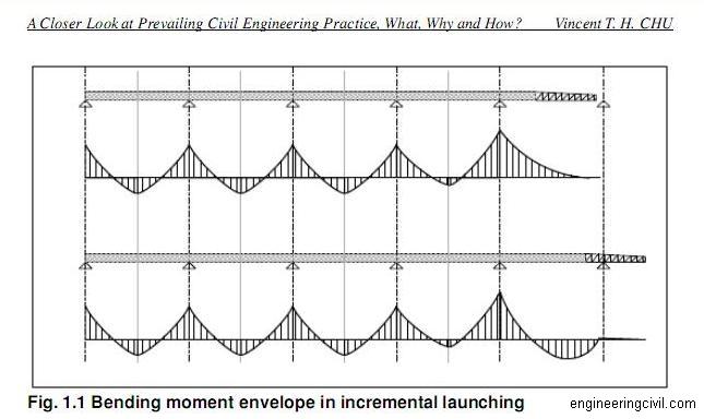
Central prestressing is normally required during construction in Incremental Launching method. Why?
-
- The erection condition plays an important role to the structural design of bridges when incremental launching method is adopted.
-
- Each section of superstructure is manufactured directly against the
preceding one and after concrete hardens, the whole structure is moved forward by the length of one section. When the superstructure is launched at prefabrication area behind one of the abutments, it is continually subjected to alternating bending moments. Each section of superstructure (about 15m to 25m long) is pushed from a region of positive moment and then to a region of negative moment and this loading cycled is repeated. As such, tensile stresses occur alternately at the bottom and top portion of superstructure section. For steel, it is of equal strength in both compression and tension and it has no difficulty in handling such alternating stress during launching process. However concrete could only resist small tensile stresses and therefore, central prestressing is carried out to reduce the tensile stress to acceptable levels.
-
- Central prestressing means that the prestressing cables are arranged such that the resultant compressive stresses at all points in a given cross section are equal and it does not matter whether tensile stresses occur in upper or lower portion of superstructure during launching process.
-
- This question is taken from book named – A Closer Look at Prevailing Civil Engineering Practice – What, Why and How by Vincent T. H. CHU.
-
-
- GENERAL
The purpose of grouting is to provide permanent protection to the post-tensioned steel against corrosion and to develop bond between the Prestressing cables and the surrounding structural concrete.Grouting shall be carried out as early as possible, but generally not later than two weeks of stressing.Whenever this stipulation cannot be completed with for unavoidable reasons adequate temporary protection of the cables against corrosion by methods or products, which will not impair the ultimate adherence of the injected grout shall be ensured till grouting.
-
- Material
1. Water : Only Clean potable water free from impurities shall be used.
2. Cement : Ordinary port land cement 43Grade shall be used. It should be as fresh as possible and free from any lumps.
3. Admixture : Non-shrink powder compound. (Intra Plast N-200 of Sika Brand).
-
- Equipments
1. Grout Mixer Mechanical type
2. Grout Pump J-600
3. Grout Screen
4. Connection and air vents
5. Generator
6. Thermometer, Stopwatch etc.
-
- Procedure of the Grout
1)After measuring the slip of 24hrs, the extended cables shall be cut off
50mm away from bearing plates.
2) Cement mortar of 1:1 ratio is applied over the Bearing Plates on both ends of girders to prevent the leakage of Grout. Grouting operation shall be commenced after two days of sealing the ends.
3) Water cement ratio should be as low as possible consistent with workability. This ratio is 0.42 (not more than 0.45 as per MOST,P-677) proportions of material shall be based on field trials made on the Grout before commencement of grouting. As per specifications, the temperature of the Grout maintained at 250C by adding ice into water if necessary.
4) Water shall be poured in to the mixer with Port land cement and admixture is added into it. Mixing shall be continued for duration to obtain uniform and thoroughly blended Grout. Grout shall be continuously agitated and then pour into another tank after passing through the screen.
5) Ducts shall be flushed with water for cleaning as well as for wetting the surface of the duct walls.
6) The water in the duct shall be blown out with compress air.
-
- Injection Of Grout:-
-
- 1) After mixing of Grout, all connections from tank to pump and pump to inlet shall be checked.
2) The grout shall be allowed to flow freely from the other end until the consistency of the grout at this end is the same as that of the Grout at the injection end.
3) When the Grout flows at the other end, it shall be closed off and grouting is continued so that pressure commenced, full injection pressure at about 5 kg/cm2 shall be maintained for at least one minute before closing the injection pipes.
4) If there is leakage observed at any of ends the grouting operation shall be discontinued and the entire duct flushed with high-pressure water. Grout not used within 30minutes of mixing shall be rejected.
6) Check the Compressive strength of the cubes for the grout in 10 cm cubes for 7 days, which should not be less than 17 Mpa.
7) Grouting record for each cable shall be maintained as per Performa in MOST.
-
- This information was submitted by Er. Neha Sood on 3d June 2008
-
No comments:
Post a Comment