Which bridge parapet is better, steel parapet or aluminum parapet?
Steel parapets normal requires painting or pre-treatment with hot-dip galvanizing as they are prone to corrosion and they are normally the cheapest choice for normal containment level of vehicles.
The initial material and setup cost of aluminum parapet is high. They are free of the problem of corrosion and the design of aluminum parapets does not require surface protection. However, owing to their high material price, care should be taken on the design to prevent stolen of parts of parapet. Moreover, aluminum parapet is lighter than steel and has weight savings over steel parapets.
This question is taken from book named – A Self Learning Manual – Mastering Different Fields of Civil Engineering Works (VC-Q-A-Method) by Vincent T. H. CHU.
What is the purpose of installation of shear keys in bridge abutment?
In small and medium sized bridges, shear keys are often designed in bridge abutments to provide transverse support to the bridge superstructure under lateral loads. They are not intended to carry vertical loads and they have important applications in resisting seismic loads.
Shear keys in bridge abutment are divided into two types, exterior or interior. Exterior shear keys have the demerit of the ease of inspection and repair. The shear keys are designed as sacrificial and it is assumed that once their capacity has been exceeded, the shear keys would not provide further support. As such, the bridge columns should be designed to provide transverse support once the shear keys fail to function.
This question is taken from book named – A Self Learning Manual – Mastering Different Fields of Civil Engineering Works (VC-Q-A-Method) by Vincent T. H. CHU.
What is the mechanism of scouring at obstructions (e.g. bridge piers) in rivers?
When the water flow in river is deflected by obstructions like bridge piers, scouring would occur arising from the formation of vortexes. The mechanism of formation of vortices is as follows: the flow hits the bridge piers and tends to move downwards. When the flow reaches the seabed, it would move in a direction opposite to its original flow direction before hitting the bridge piers. Hence, this movement of flow before the bridge piers results in the formation of a vortex. Owing to the formation of this vertical vortex, seabed material is continuously removed so that holes are formed at the seabed and this result in local scour at bridge piers. As the shape of vortices looks like horseshoes, it is sometimes called “horseshoe vortex”.
This question is taken from book named – A Self Learning Manual – Mastering Different Fields of Civil Engineering Works (VC-Q-A-Method) by Vincent T. H. CHU.
This question is taken from book named – A Self Learning Manual – Mastering Different Fields of Civil Engineering Works (VC-Q-A-Method) by Vincent T. H. CHU.
What are the effects of bridge piers across a stream?
The presence of bridge piers across a stream causes constricted flow in the openings because of the decrease of width of stream owing to the presence of the piers. Moreover, it creates the following problems from hydraulic point of view:
(i) Local scouring at the piers and bed erosion may take place. To avoid the damage to the foundation of piers, some protective layers of stone or concrete apron could be provided around the piers.
(ii) The head loss induced by the bridge piers causes the backwater effect so that the water level upstream is increased. Consequently, this may result in flooding in upstream areas.
This question is taken from book named – A Self Learning Manual – Mastering Different Fields of Civil Engineering Works (VC-Q-A-Method) by Vincent T. H. CHU.
In bridge columns, why are stirrups be placed around the vertical reinforcement?
In uniaxial compression test of concrete, upon reaching the ultimate load failure of concrete occurs where major cracks line up in the vertical direction and the concrete cube would be split up. The development of vertical cracks involves the expansion of concrete in lateral directions. In case the concrete is confined in lateral directions, it was observed that the formation of vertical cracks would be hindered as indicated in past experiments. As a result, the concrete strength is increased with also a rise in failure strain.
The above theory is often used in the design of bridge columns. Steel stirrups are installed at around the vertical main reinforcement. Other than the function of shear reinforcement, it helps to avoid the lateral deformation of interior concrete core so that the strength of concrete column is increased.
The above theory is often used in the design of bridge columns. Steel stirrups are installed at around the vertical main reinforcement. Other than the function of shear reinforcement, it helps to avoid the lateral deformation of interior concrete core so that the strength of concrete column is increased.
What is the purpose of providing a barrier around the bridge piers?
Accidental collision of heavy vehicles such as tractor-trailer with bridge piers is not uncommon around the world. The consequence of such collision is catastrophic which may involve the collapse of bridges and loss of human lives. As such, suitable provisions are made to protect bridge piers against these accidental collisions. The most common way is to install a crashworthy barrier which should be designed to be capable of resisting the impact of heavy vehicles. Alternatively, in some countries such as the United States, they tend to revise the design of bridge barriers by requiring the bridge piers to be able to resist the collision of 1,800kN static force at 1.35m above ground.
This question is taken from book named – A Self Learning Manual – Mastering Different Fields of Civil Engineering Works (VC-Q-A-Method) by Vincent T. H. CHU.
This question is taken from book named – A Self Learning Manual – Mastering Different Fields of Civil Engineering Works (VC-Q-A-Method) by Vincent T. H. CHU.
What are the purposes of waterproofing in bridge decks?
Waterproofing materials like membranes are applied on top of bridge deck surface because:
(i) Vehicular traffic (e.g. tanker) may carry dangerous chemicals and the leakage of such chemicals in the absence of waterproofing materials may endanger the life of bridges. The chemicals easily penetrate and cause the deterioration of concrete bridge decks.
(ii) In some countries where very cold weather is frequently encountered, salt may be applied for defrosting purpose. In case waterproofing is not provided, the salt solution penetrates through the concrete cracks of the bridge and causes the corrosion of reinforcement.
(iii) In the event of cracks appearing on concrete deck, water penetrates the bridge deck and brings about steel corrosion.
This question is taken from book named – A Self Learning Manual – Mastering Different Fields of Civil Engineering Works (VC-Q-A-Method) by Vincent T. H. CHU.
What is the purpose of overlays on concrete bridge deck?
After years of servicing, some overlays may be applied on the top surface of bridges. Overlays on concrete bridge decks achieve the following purposes:
(i) It aims to provide a smooth riding surface. Hence, it may be applied during the maintenance operation to hide the uneven and spalling deck surface and offers a smoother surface for road users.
(ii) The use of overlays can extend the life of the bridge deck.
This question is taken from book named – A Self Learning Manual – Mastering Different Fields of Civil Engineering Works (VC-Q-A-Method) by Vincent T. H. CHU.
What are the problems of using transition slabs in bridges?
In some designs, transition slabs are provided on the approach to bridges. For instance, soils in embankment supporting the roads may settle due to insufficient compaction and sharp depressions would be developed at the junction with the relatively rigid end of bridge decks. This creates the problem of poor riding surfaces of carriageway and proper maintenance has to be carried out to rectify the situation. As a result, transition slabs are sometimes designed at these junctions to distribute the relative settlements between the approaching embankments and end of bridge decks so that the quality of riding surface between these junctions could be significantly improved and substantial savings could be obtained by requiring less maintenance.
This question is taken from book named – A Self Learning Manual – Mastering Different Fields of Civil Engineering Works (VC-Q-A-Method) by Vincent T. H. CHU.
This question is taken from book named – A Self Learning Manual – Mastering Different Fields of Civil Engineering Works (VC-Q-A-Method) by Vincent T. H. CHU.
How do engineer determine the number of cells for concrete box girder bridges?
If the depth of a box girder bridge exceeds 1/6 or 1/5 of the bridge width, then it is recommended to be designed as a single cell box girder bridge. However, if the bridge depth is smaller than 1/6 of the bridge width, then a twin-cell or multiple cell is a better choice as suggested by Jorg Schlaich & Hartmut Scheef (1982). However, one should note that even for wider bridges with small depths, the number of cells should be minimized because there is not much improvement in transverse load distribution when the number of cells of box girder is increased to three or more.
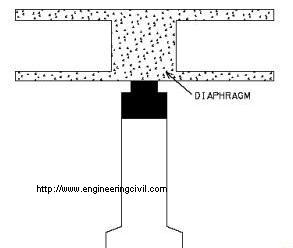
Are diaphragms necessary in the design of concrete box girder bridges?
Diaphragms are adopted in concrete box girder bridges to transfer oads from bridge decks to bearings. Since the depth of diaphragms normally exceeds the width by two times, they are usually designed as deep beams. However, diaphragms may not be necessary in case bridge bearings are placed directly under the webs because loads in bridge decks can be directly transferred to the bearings based on Jorg Schlaich & Hartmut Scheef (1982). This arrangement suffers from the drawback that changing of bearings during future maintenance operation is more difficult.
In fact, diaphragms also contribute to the provision of torsional restraint to the bridge deck.
This question is taken from book named – A Self Learning Manual – Mastering Different Fields of Civil Engineering Works (VC-Q-A-Method) by Vincent T. H. CHU.
In fact, diaphragms also contribute to the provision of torsional restraint to the bridge deck.
This question is taken from book named – A Self Learning Manual – Mastering Different Fields of Civil Engineering Works (VC-Q-A-Method) by Vincent T. H. CHU.
What are the functions of diaphragms in bridges?
Diaphragm is a member that resists lateral forces and transfers loads to support. Some of the diaphragms are post-tensioned and some contain normal reinforcement. It is needed for lateral stability during erection and for resisting and transferring earthquake loads. Based on past research, diaphragms are ineffective in controlling deflections and reducing member stresses. Moreover, it is commonly accepted that diaphragms aided in the overall distribution of live loads in bridges.
The main function of diaphragms is to provide stiffening effect to deck slab in case bridge webs are not situated directly on top of bearings. Therefore, diaphragms may not be necessary in case bridge bearings are placed directly under the webs because loads in bridge decks can be directly transferred to the bearings. On the other hand, diaphragms also help to improve the load-sharing characteristics of bridges. In fact, diaphragms also contribute to the provision of torsional restraint to the bridge deck.
This question is taken from book named – A Self Learning Manual – Mastering Different Fields of Civil Engineering Works (VC-Q-A-Method) by Vincent T. H. CHU.
What are the advantages of assigning the central pier and the abutment as fixed piers?
(i) For abutment pier to be assigned as fixed pier while the bridge is quite long, the longitudinal loads due to earthquake are quite large. As the earthquake loads are resisted by fixed piers, the size of fixed piers will be large and massive. In this connection, for better aesthetic appearance, the selection of abutment as fixed piers could accommodate the large size and massiveness of piers. Normally abutments are relatively short in height and for the same horizontal force, the bending moment induced is smaller.
(ii) For the central pier to be selected as the fixed pier, the bridge deck is allowed to move starting from the central pier to the end of the bridge. However, if the fixed pier is located at the abutment, the amount of movement to be incorporated in each bearing due to temperature variation, shrinkage, etc. is more than that when the fixed pier is located at central pier. Therefore, the size of movement joints can be reduced significantly.
This question is taken from book named – A Self Learning Manual – Mastering Different Fields of Civil Engineering Works (VC-Q-A-Method) by Vincent T. H. CHU.
How does the position of bearing affect the continuity of joints?
Expansion joints in a bridge structures cater for movements in transverse, longitudinal, vertical and rotational forms. The layout and position of expansion joins and bearings have to be carefully designed to minimize the future maintenance problem.
The position of bearings affects the discontinuity of a joint. If the
location of a bearing is too far away from a bridge joint, discontinuity of the joint would be experienced when there is an excessive angular rotation at the joint. Hence, by keeping the bearings and movement joints close in position, the discontinuity in the vertical direction can be avoided.

This question is taken from book named – A Self Learning Manual – Mastering Different Fields of Civil Engineering Works (VC-Q-A-Method) by Vincent T. H. CHU.
The position of bearings affects the discontinuity of a joint. If the
location of a bearing is too far away from a bridge joint, discontinuity of the joint would be experienced when there is an excessive angular rotation at the joint. Hence, by keeping the bearings and movement joints close in position, the discontinuity in the vertical direction can be avoided.
This question is taken from book named – A Self Learning Manual – Mastering Different Fields of Civil Engineering Works (VC-Q-A-Method) by Vincent T. H. CHU.
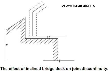
How will inclined bridge deck affect joint continuity?
Bearings are usually designed to sit in a horizontal plane so as to avoid the effect of additional horizontal force and uneven pressure distribution resulting from non-horizontal placing of bearings [43]. For an inclined bridge deck subject to a large longitudinal movement, a sudden jump is induced at the expansion joint and discontinuity of joint results. To solve this problem, an inclined bearing instead of a truly horizontal bearing is adopted if the piers can take up the induced horizontal forces.
Why are excessive movement joints undesirable in bridges?
Movement joints are normally added to bridge structures to accommodate movements due to dimensional changes arising from temperature variation, shrinkage, creep and effect of prestress. However, the provision of excessive movement joints should be avoided in design because movement joints always encounter problems giving rise to trouble in normal operation and this increases the cost of maintenance.
Some designers may prefer to add more movement joints to guard against possible occurrence of differential settlements. However, the effect of continuity is disabled by this excessive introduction of movement joints. In essence, the structural reserve provided by a continuous bridge is destroyed by the multiple-span statically determinate structure resulting from the addition of excessive joints.
This question is taken from book named – A Self Learning Manual – Mastering Different Fields of Civil Engineering Works (VC-Q-A-Method) by Vincent T. H. CHU.
What is the advantage of sliding bearings over roller bearings?
In roller bearing for a given movement the roller bearing exhibit a change in pressure centre from its original position by one-half of its movement based on David J. Lee. However, with sliding bearing a sliding plate is attached to the upper superstructure and the moving part of bearing element is built in the substructure. It follows that there is no change in pressure center after the movement.
This question is taken from book named – A Self Learning Manual – Mastering Different Fields of Civil Engineering Works (VC-Q-A-Method) by Vincent T. H. CHU.
This question is taken from book named – A Self Learning Manual – Mastering Different Fields of Civil Engineering Works (VC-Q-A-Method) by Vincent T. H. CHU.
For elastomeric bearings, which shape is better, rectangular or circular?
Circular bearings have the advantage for standardization because only one dimension can vary in plan. They are suitable for use in curved and large skewed bridge as they could accommodate movement and rotations in multiple directions.
Rectangular bearings are suitable for low skewed bridges. In particular, it is best suited in bridges with large rotations and movements
This question is taken from book named – A Self Learning Manual – Mastering Different Fields of Civil Engineering Works (VC-Q-A-Method) by Vincent T. H. CHU.
Rectangular bearings are suitable for low skewed bridges. In particular, it is best suited in bridges with large rotations and movements
This question is taken from book named – A Self Learning Manual – Mastering Different Fields of Civil Engineering Works (VC-Q-A-Method) by Vincent T. H. CHU.
What is the importance of shear stiffness in the design of elastomeric bearing?
For elastomeric bearing, the shear stiffness is an important parameter for design because it influences the force transfer between the bridge and its piers. In essence, elastomers are flexible under shear deformation but it is relatively stiff in compression. However, elastomeric bearings should not be used in tension.
Elastomeric bearing should be designed in serviceability limit state only. The cross sectional area is normally determined by the compressive stress limit under serviceability limit state. The shape factor, i.e. plan area of the laminar layer divided by area of perimeter free to bulge, affects the relation and the compressive load. In essence, higher
capacity of bearings could be obtained with higher shape factor.
The long side of the bearing is usually oriented parallel to the principle axis of rotation because it facilitates rotational movement. The thickness of bearings is limited and controlled by shear strain requirements. In essence, the shear strain should be less than a certain limit to avoid the occurrence of rolling over at the edges and delamination due to fatigue. Hence, it follows that higher rotations and translations require thicker bearing. On the other hand, the vertical stiffness of bearings is obtained by inserting sufficient number of steel plates. In addition, checks should be made on combined compression and rotation to guard against the possible occurrence of uplifting of corners of bearings under certain load combinations.
This question is taken from book named – A Self Learning Manual – Mastering Different Fields of Civil Engineering Works (VC-Q-A-Method) by Vincent T. H. CHU.
Why do some engineers prefer to use neoprene instead of natural rubber in elastomeric bearings?
Some engineers may choose to design elastomeric bearings to sit on the piers without a connection. The bearing is held in place by frictional resistance only. Paraffin used in natural rubber would bleed out and result in significant decrease in friction. As such, elastomeric bearings would slip away and walk out from their original locations. To solve this problem, neoprene, instead of natural rubber, is used as elastomer because paraffin is absent in neoprene bearings.
In the design of elastomeric bearings, why are steel plates inserted inside the bearings?
For elastomeric bearing to function as a soft spring, the bearing should be allowed for bulging laterally and the compression stiffness can be increased by limiting the amount of lateral bulging. To increase the compression stiffness of elastomeric bearings, metal plates are inserted.
After the addition of steel plates, the freedom to bulge is restricted and the deflection is reduced when compared with bearings without any steel plates under the same load. Tensile stresses are induced in these steel plates during their action in limiting the bulging of the elastomer. This in turn would limit the thickness of the steel plates.
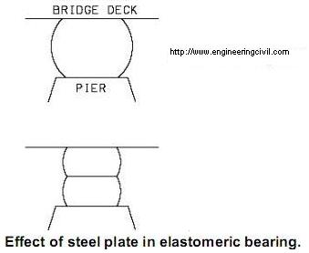
However, the presence of metal plates does not affect the shear stiffness of the elastomeric bearings.
This question is taken from book named – A Self Learning Manual – Mastering Different Fields of Civil Engineering Works (VC-Q-A-Method) by Vincent T. H. CHU.
After the addition of steel plates, the freedom to bulge is restricted and the deflection is reduced when compared with bearings without any steel plates under the same load. Tensile stresses are induced in these steel plates during their action in limiting the bulging of the elastomer. This in turn would limit the thickness of the steel plates.
However, the presence of metal plates does not affect the shear stiffness of the elastomeric bearings.
This question is taken from book named – A Self Learning Manual – Mastering Different Fields of Civil Engineering Works (VC-Q-A-Method) by Vincent T. H. CHU.
How to determine the size of elastomeric bearings?
For elastomeric bearing, the vertical load is resisted by its compression while shear resistance of the bearing controls the horizontal movements.
The design of elastomeric bearings is based on striking a balance between the provision of sufficient stiffness to resist high compressive force and the flexibility to allow for translation and rotation movement.
The cross sectional area is normally determined by the allowable pressure on the bearing support. Sometimes, the plan area of bearings is controlled by the maximum allowable compressive stress arising from the consideration of delamination of elastomer from steel plates. In addition, the size of elastomeric bearings is also influenced by considering the separation between the structure and the edge of bearing which may occur in rotation because tensile stresses deriving from separation may cause delamination. The thickness of bearings is designed based on the limitation of its horizontal stiffness and is controlled by movement requirements. The shear strain should be less than a certain limit to avoid the occurrence of rolling over and fatigue damage. The vertical stiffness of bearings is obtained by inserting sufficient number of steel plates.
This question is taken from book named – A Self Learning Manual – Mastering Different Fields of Civil Engineering Works (VC-Q-A-Method) by Vincent T. H. CHU.
What is the purpose of dowel bar in elastomeric bearing?
Elastomeric bearing is normally classified into two types: fixed and free. For fixed types, the bridge deck is permitted only to rotate and the horizontal movements of the deck are restrained. On the other hand, for free types the deck can move horizontally and rotate. To achieve fixity, dowels are adopted to pass from bridge deck to abutment. Alternatively, in case there is limitation in space, holes are formed in the elastomeric bearings where anchor dowels are inserted through these holes. It is intended to prevent the “walking” of the bearing during its operation.
This question is taken from book named – A Self Learning Manual – Mastering Different Fields of Civil Engineering Works (VC-Q-A-Method) by Vincent T. H. CHU.
This question is taken from book named – A Self Learning Manual – Mastering Different Fields of Civil Engineering Works (VC-Q-A-Method) by Vincent T. H. CHU.
What is the purpose of dimples in PTFE in bridge bearings?
PTFE is a flurocarbon polymer which possesses good chemical resistance and can function in a wide range of temperature. The most important characteristic of this material is its low coefficient of friction. PTFE has the lowest coefficients of static and dynamic friction of any solid with absence of stick-slip movement. The coefficient of friction is found to decrease with an increase in compressive stress. However, PTFE do have some demerits like high thermal expansion and low compressive strength.
In designing the complementary contact plate with PTFE sliding surface, stainless steel plates are normally selected where the plates should be larger than PTFE surface to allow movement without exposing the PTFE. Moreover, it is recommended that the stainless steel surface be positioned on top of the PTFE surface to avoid contamination by possible accumulation of dirt and rubbish on the larger lower plates. Lubricants are sometimes introduced to reduce the friction between the PTFE surface and the upper stainless steel plate. Dimples are designed on PTFE surfaces to act as reservoirs for lubricant and these reservoirs are uniformly distributed over the surface of PTFE and normally they cover about 20%-30% of the
surface area. Hence, the PTFE may be designed with dimples to avoid the lubricant from squeezing out under repeated translation movements.
This question is taken from book named – A Self Learning Manual – Mastering Different Fields of Civil Engineering Works (VC-Q-A-Method) by Vincent T. H. CHU.
Polytetrafluoroethylene (PTFE) is commonly used in sliding bearings. Why?
The choice of sliding surface of bearings is of vital importance because the sliding surfaces generate frictional forces which are exerted on the bearings and substructure of the bridge. For instance, PTFE and lubricated bronze are commonly choices of sliding surfaces for bearings. PTFE is a flurocarbon polymer which possesses good chemical resistance and can function in a wide range of temperature. The most important characteristic of this material is its low coefficient of friction. PTFE has the lowest coefficients of static and dynamic friction of any solid with absence of stick-slip movement (David J. Lee). The coefficient of friction is found to decrease with an increase in compressive stress. However, PTFE do have some demerits like high thermal expansion and low compressive strength.
In designing the complementary contact plate with PTFE sliding surface, stainless steel plates are normally selected where the plates should be larger than PTFE surface to allow movement without exposing the PTFE. Moreover, it is recommended that the stainless steel surface be positioned on top of the PTFE surface to avoid contamination of dirt and rubbish. Lubricants are sometimes introduced to reduce the friction between the PTFE surface and the upper stainless steel plate. Hence, the PTFE may be designed with dimples to avoid the lubricant from squeezing out under repeated translation movements.
In designing the complementary contact plate with PTFE sliding surface, stainless steel plates are normally selected where the plates should be larger than PTFE surface to allow movement without exposing the PTFE. Moreover, it is recommended that the stainless steel surface be positioned on top of the PTFE surface to avoid contamination of dirt and rubbish. Lubricants are sometimes introduced to reduce the friction between the PTFE surface and the upper stainless steel plate. Hence, the PTFE may be designed with dimples to avoid the lubricant from squeezing out under repeated translation movements.
Why do most elastomers used in pot bearing are usually contained?
To specify space requirements, most pot bearings are designed for high contact pressures with small contact area with bridges. This also enhances lower friction values. Under the free state, most elastomers in pot bearings can hardly sustain this high pressure and hence they are most contained to prevent overstraining. When properly constrained, the elastomer behaves like semi-viscous fluid and can safely accommodate angular displacement.
This question is taken from book named – A Self Learning Manual – Mastering Different Fields of Civil Engineering Works (VC-Q-A-Method) by Vincent T. H. CHU.
This question is taken from book named – A Self Learning Manual – Mastering Different Fields of Civil Engineering Works (VC-Q-A-Method) by Vincent T. H. CHU.
Under what situation should engineers use pot bearings instead of elastomeric bearings?
In the event of high vertical loads combined with large angle of rotations, rubber bearings are undesirable when compared with pot bearings. For instance, elastomeric bearings require large bearing surfaces so that compression can be maintained between the contact surfaces between the bearings and piers. Moreover, it also leads to uneven distribution of stress on the piers and some of these highly induced stresses may damage the piers. Consequently, pot bearings are better alternatives than elastomeric bearings in such an scenario as suggested by David J. Lee.
This question is taken from book named – A Self Learning Manual – Mastering Different Fields of Civil Engineering Works (VC-Q-A-Method) by Vincent T. H. CHU.
This question is taken from book named – A Self Learning Manual – Mastering Different Fields of Civil Engineering Works (VC-Q-A-Method) by Vincent T. H. CHU.
What is preset in bridge bearing?
“Preset” is a method to reduce the size of upper plates of sliding bearings in order to save cost.
The normal length of an upper bearing plate should be composed of the following components = length of bearing + 2xirreversible movement + 2xreversible movement.
Initially the bearing is placed at the mid-point of the upper bearing plate without considering the directional effect of irreversible movement. However, as irreversible movement normally takes place at one direction only, the bearing is displaced/presetted a distance of (irreversible movement/2) from the mid-point of bearing in which the length of upper plate length is equal to the length of bearing + irreversible movement + 2 x reversible movement. In this arrangement, the size of upper plate is minimized in which irreversible movement takes place in one direction only and there is no need to include the component of two irreversible movements in the upper plate.
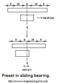
Note: “Preset” refers to the displacement of a certain distance of sliding bearings with respect to upper bearing plates during installation of bearings.
This question is taken from book named – A Self Learning Manual – Mastering Different Fields of Civil Engineering Works (VC-Q-A-Method) by Vincent T. H. CHU.
The normal length of an upper bearing plate should be composed of the following components = length of bearing + 2xirreversible movement + 2xreversible movement.
Initially the bearing is placed at the mid-point of the upper bearing plate without considering the directional effect of irreversible movement. However, as irreversible movement normally takes place at one direction only, the bearing is displaced/presetted a distance of (irreversible movement/2) from the mid-point of bearing in which the length of upper plate length is equal to the length of bearing + irreversible movement + 2 x reversible movement. In this arrangement, the size of upper plate is minimized in which irreversible movement takes place in one direction only and there is no need to include the component of two irreversible movements in the upper plate.
Note: “Preset” refers to the displacement of a certain distance of sliding bearings with respect to upper bearing plates during installation of bearings.
This question is taken from book named – A Self Learning Manual – Mastering Different Fields of Civil Engineering Works (VC-Q-A-Method) by Vincent T. H. CHU.
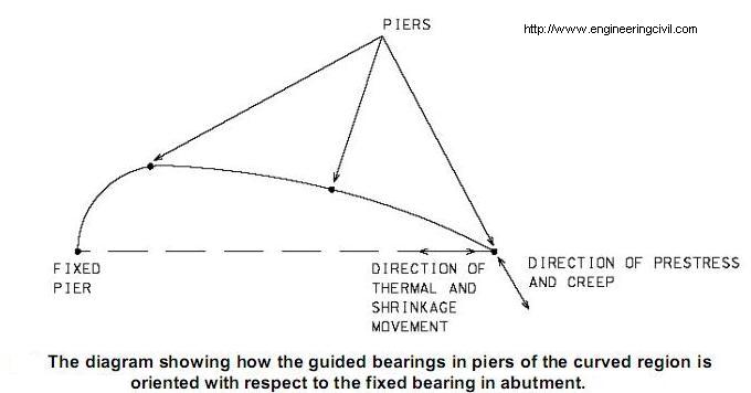
In a curved prestressed bridge, how should the guided bearings in piers of the curved region be oriented with respect to the fixed bearing in abutment?
To determine the orientation of guided bearings, one should understand the movement of curved region of a prestressed bridge. Movement of prestress and creep are tangential to the curvature of the bridge (or along longitudinal axis) while the movement due to temperature and shrinkage effects are in a direction towards the fixed pier. If the direction of guided bearings is aligned towards the fixed bearing in the abutment, the difference in direction of pretress and creep movement and the guided direction towards fixed bearing would generate a locked-in force in the bridge system. The magnitude of the lock-in force is dependent on the stiffness of deck and supports. If the force is small, it can be designed as additional force acting on the support and deck. However, if the force is large, temporary freedom of movement at the guided bearings has to be provided during construction.
This question is taken from book named – A Self Learning Manual – Mastering Different Fields of Civil Engineering Works (VC-Q-A-Method) by Vincent T. H. CHU.
This question is taken from book named – A Self Learning Manual – Mastering Different Fields of Civil Engineering Works (VC-Q-A-Method) by Vincent T. H. CHU.
In joints of precast concrete bridge segments, what are the functions of applying epoxy adhesive?
Epoxy adhesive is applied in these joints for the following purposes according to International Road Federation (1977):
(i) It seals up the joints completely between precast concrete segments to protect the prestressing tendons;
(ii) By filling voids and irregularities along the segment joints, it helps reduce stress concentrations otherwise it will be developed; and
(iii) It helps in transferring of shear between the joints in case a large single shear key is used.
In bridge widening projects, the method of stitching is normally employed for connecting existing deck to the new deck. What are the problems associated with this method in terms of shrinkage of concrete?
In the method of stitching, it is a normal practice to construct the widening part of the bridge at first and let it stay undisturbed for several months. After that, concreting will then be carried out for the stitch between the existing deck and the new deck. In this way, the dead load of the widened part of bridge is supported by itself and loads arising from the newly constructed deck will not be transferred to the existing deck which is not designed to take up these extra loads.
One of the main concerns is the effect of stress induced by shrinkage of newly widened part of the bridge on the existing bridge. To address this problem, the widened part of the bridge is constructed a period of time (say 6-9 months) prior to stitching to the existing bridge so that shrinkage of the new bridge will take place within this period and the effect of shrinkage stress exerted on the new bridge is minimized.
Traffic vibration on the existing bridge causes adverse effect to the freshly placed stitches. To solve this problem, rapid hardening cement is used for the stitching concrete so as to shorten the time of setting of concrete. Moreover, the stitching work is designed to be carried out at nights of least traffic (Saturday night) and the existing bridge may even be closed for several hours (e.g. 6 hours) to let the stitching works to left undisturbed.
Sometimes, longitudinal joints are used in connecting new bridge segments to existing bridges. The main problem associated with this design is the safety concern of vehicles. The change of frictional coefficients of bridge deck and longitudinal joints when vehicles change traffic lanes is very dangerous to the vehicles. Moreover, maintenance of longitudinal joints in bridges is quite difficult.
Note: Stitching refers to formation of a segment of bridge deck between an existing bridge and a new bridge.
This question is taken from book named – A Self Learning Manual – Mastering Different Fields of Civil Engineering Works (VC-Q-A-Method) by Vincent T. H. CHU.
In incremental launching method of bridge construction, what are the measures adopted to enhance sufficient resistance of the superstructure during the launching process?
(i) During the launching process the leading edge of the superstructure is subject to a large hogging moment. In this connection, steel launching nose typically about 0.6-0.65 times span length is provided at the leading edge to reduce the cantilever moment. Sometimes, instead of using launching nose a tower and stay system are designed which serves the same purpose.
(ii) The superstructure continually experiences alternative sagging and hogging moments during incremental launching. Normally, a central prestress is provided in which the compressive stress at all points of bridge cross section is equal. In this way, it caters for the possible occurrence of tensile stresses in upper and lower part of the cross section when subject to hogging and sagging moment respectively. Later when the whole superstructure is completely launched, continuity prestressing is performed in which the location and design of continuity tendons are based on the bending moments in final completed bridge condition and its provision is supplementary to the central prestress.
(iii) For very long span bridge, temporary piers are provided to limit the
cantilever moment.
This question is taken from book named – A Self Learning Manual – Mastering Different Fields of Civil Engineering Works (VC-Q-A-Method) by Vincent T. H. CHU.
In the construction of a two-span bridge (span length = L) by using span-by-span construction, why is a length of about 1.25L bridge segment is constructed in the first phase of construction?
Basically, there are mainly three reasons for this arrangement:
(i) The permanent structure is a statically indeterminate structure. During construction by using span-by-span construction, if the first phase of construction consists of the first span length L only, then the sagging moment in the mid span of the partially completed bridge is larger than that of completed two-span permanent structure. To avoid such occurrence, 0.25L of bridge segment is extended further from the second pier which provides a counteracting moment, thereby reducing the mid-span moment of the partially completed bridge.
(ii) The position of 1.25 L countering from the first pier is the approximate location of point of contraflexure (assume that the two-span bridge is uniformly loaded) in which the bridge moment is about zero in the event of future loaded bridge. Therefore, the design of construction joint in this particular location has the least adverse effect on the structural performance of the bridge.
(iii) In case of a prestressed bridge, prestressing work has to be carried out after the construction of first segment of the bridge. If the prestressing work is conducted at the first pier which is heavily
reinforced with reinforcement, it is undesirable when compared with the prestressing location at 1.25L from the first pier where there is
relatively more space to accommodate prestressing works.
Note: Span-by-span construction means that a bridge is constructed from one bridge span to another until its completion.
This question is taken from book named – A Self Learning Manual – Mastering Different Fields of Civil Engineering Works (VC-Q-A-Method) by Vincent T. H. CHU.
What are the potential advantages in using lightweight aggregates in bridges?
The advantages in using in using lightweight aggregates in bridges:
(i) Owing to reduced dead load by using lightweight aggregates, there are savings in structural material such as the cost of foundation and
falsework.
(ii) It brings about environmental benefits when industrial waste products are used to manufacture lightweight aggregates.
(iii) It enhances higher durability by having lower coefficient of thermal expansion which reduces the thermal movement. Moreover, it has lower permeability and higher resistance to freeze-thaw cycles when compared with normal aggregates.
This question is taken from book named – A Self Learning Manual – Mastering Different Fields of Civil Engineering Works (VC-Q-A-Method) by Vincent T. H. CHU.
When would torsional stiffness of members be considered in analyzing a bridge?
If a box-girder type bridge is purposely chosen because of its torsional strength, then the torsional stiffness and resistance should be considered in design. However, it is commonly accepted to assume that torsional stiffness of a beam to be negligible so that it saves the complexity to provide reinforcement to resist torsion. As such, this would result in higher bending moments induced in the beam.
If the torsional stiffness has been incorporated in computer model during the structural analysis, then it is necessary to check the torsional resistance of the beam.
If the torsional stiffness has been incorporated in computer model during the structural analysis, then it is necessary to check the torsional resistance of the beam.
Should at-rest, active or passive soil pressure be used in the design of abutment?
At-rest soil pressure is developed during the construction of bridge abutment. Active soil pressure are developed when the abutment are pushed forward by backfilled soils at the back of abutment wall. A state of equilibrium shall be reached when the at-rest pressure is reduced to active earth pressure. Hence, at-rest pressure is considered when assessing the stability of abutment while active pressure is adopted when assessing the adequacy of structural elements of abutment.
Passive pressure is only considered in integral abutment which experiences passive pressure when the deck expands under thermal effects.
Passive pressures are developed when the abutment wall pushes the soils at the front of abutment. Given that larger movements is required to mobilize passive pressure than active pressure and the abutment is designed not to slide under active pressure, it is normally assumed that passive pressure does not develop at the front of abutment. Moreover, there is a possibility that soils may be removed temporarily owing to utility diversion; it is normally assumed that stability contribution by soils in front of abutment is ignored.
This question is taken from book named – A Self Learning Manual – Mastering Different Fields of Civil Engineering Works (VC-Q-A-Method) by Vincent T. H. CHU.
How to estimate the earth pressure on abutment?
The magnitude of earth pressure coefficient in calculating the earth pressure on bridge abutment depends significantly on the degree of restraint provided by the abutment. For example, active earth pressure is usually adopted for cantilever abutment because there is possible occurrence of small relieving movements. However, for abutment founded on piles, the at-rest earth pressure can be assumed in assessing the earth pressure as the abutment is considered to be rigidly supported by piles and is fully restrained against lateral movement.
This question is taken from book named – A Self Learning Manual – Mastering Different Fields of Civil Engineering Works (VC-Q-A-Method) by Vincent T. H. CHU.
This question is taken from book named – A Self Learning Manual – Mastering Different Fields of Civil Engineering Works (VC-Q-A-Method) by Vincent T. H. CHU.
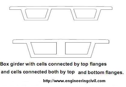
What is the effect of shear lag in a typical box-girder bridge?
For multiple-cell box girders, there are generally two arrangements. The first one is that independent cells are connected by their top flanges only while the other one is that the cells are connected both at the top and bottom flanges. From the structural point of view, it is recommended to adopt the second arrangement. For the case of cells connected by top flanges only, their flanges are heavily stressed in the transverse direction owing to flexure which cannot be effectively distributed across the cross section.
In the structural analysis of bridges, shear lag have to be considered in design in some circumstances. Shear lag takes place when some parts of the cross section are not directly connected. For a box-girder bridge, not all parts of flanges are joined directly to webs so that the connected part becomes highly stressed while the unconnected flanges are not fully stressed. In particular, for wide flanges of box-girder bridges axial loads are transferred by shear from webs to flanges which result in the distortion in their planes. Consequently, the plane sections do not stay plane and the stress distribution in the flanges are not uniform. Moreover, there is a tendency for longitudinal in-plane displacements of bride deck away from the flange/web connection to lag behind those parts of the bridge in close vicinity to the flange/web connection.
The effect of shear lag causes the longitudinal stress at flange/web connection to be higher than the mean stress across the flange. Therefore, the effect of shear lag has to be catered for in the design of box-girder bridges, especially for those with wide flanges.
This question is taken from book named – A Self Learning Manual – Mastering Different Fields of Civil Engineering Works (VC-Q-A-Method) by Vincent T. H. CHU.
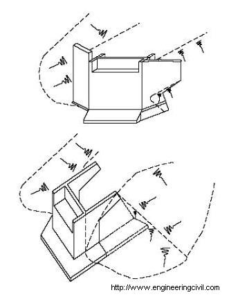
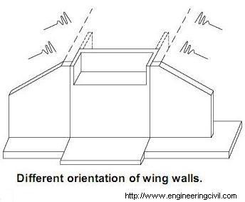
What is the consideration in selecting the orientation of wing walls in the design of bridge abutments?
There are three common arrangements of wing walls in bridge abutments based on Dr. Edmund C Hambly (1979):
(i) Wing walls parallel to abutments
This is the simplest and shortest time to build but is not the most economical design. This design has the advantage that it has least disturbance to existing slope embankment.
(ii) Wing walls at an angle to abutments
This is the most economical design among the three options in terms of material cost.
(iii) Wing walls perpendicular to abutments
Though it is not the most economical design, the wing walls provide a continuous alignment with bridge decks which provide supports to parapets.
However, they cause disturbances to adjacent structures and utility services during construction. Moreover, if the bridge is curved, the wing walls may hinder the road curvature.
One the other hand, when the wing walls are structurally connected to the abutment, then structural advantage can be taken by the stability of box structure.
This question is taken from book named – A Self Learning Manual – Mastering Different Fields of Civil Engineering Works (VC-Q-A-Method) by Vincent T. H. CHU.
Why is the span length ratio of end span/approach span to its neighboring inner spans usually about 0.75?
From aesthetic point of view, an odd number of spans with a decrease in length in the direction of abutment is desirable. Moreover, spans of equal length are found to be boring. However, the arrangement of irregular span lengths is not recommended because it gives a feeling of uneasiness.
From structural point of view, for a multi-span bridge with equal span length, the sagging moment at the mid-span of the end span/approach span is largest. In order to reduce this moment, the span length of end
span/approach span is designed to be 0.75 of inner spans. However, this ratio should not be less than 0.40 because of the effect of uplifting at the end span/approach span support.
Note: End span refers to the last span in a continuous bridge while approach span refers to the first span of a bridge.
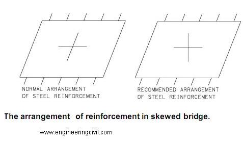
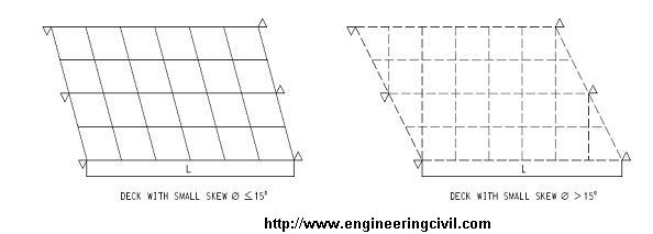
In the design of a simply supported skew bridge, which direction of reinforcement should be provided?
In the conventional design of steel reinforcement for a simply supported skew bridge, a set of reinforcement is usually placed parallel to free edge while the other set is designed parallel to the fixed edge. However, this kind of arrangement is not the most efficient way of placing the reinforcement. The reason is that in some parts of the bridge, the moment of resistance is provided by an obtuse angle formed by the reinforcement bars which is ineffective in resisting flexure. In fact, the most efficient way of the arrangement of reinforcement under most loading conditions is to place one set of bars perpendicular to the fixed edge while placing the other set parallel to the fixed end as recommended by L. A. Clark (1970). In this way, considerable savings would be obtained from the orthogonal arrangement of reinforcement.
This question is taken from book named – A Self Learning Manual – Mastering Different Fields of Civil Engineering Works (VC-Q-A-Method) by Vincent T. H. CHU.
This question is taken from book named – A Self Learning Manual – Mastering Different Fields of Civil Engineering Works (VC-Q-A-Method) by Vincent T. H. CHU.
What are the limitations of grillage analysis?
In designing the number of cells for concrete box girder bridges, in case the depth of a box girder bridge exceeds 1/6 or 1/5 of the bridge width, then it is recommended to be designed as a single cell box girder bridge. However, if the bridge depth is smaller than 1/6 of the bridge width, then a twin-cell or multiple cell is a better. However, one should note that even for wider bridges with small depths, the number of cells should be minimized because there is not much improvement in transverse load distribution when the number of cells of box girder is increased to three or more.
For structural analysis of bridges, grillage analysis, which involves the structure to be modeled as a series of longitudinal and transverse elements which are interconnected at nodes, is normally adopted.
Grillage analysis suffers from the following shortcomings based on E. C. Hambly:
(i) For coarse mesh, torques may not be identical in orthogonal directions. Similarly, twists may differ in orthogonal directions.
(ii) Moment in any beams is mainly proportional to its curvature only. However, moment in an element depends on the curvatures in the beam’s direction and its orthogonal direction.
Grillage analysis cannot be used to determine the effect of distortion and warping. Moreover, the effect of shear lag can hardly be assessed by using grillage analysis. By using fine mesh of elements, local effects can be determined with a grillage. Alternatively, the local effects can be assessed separately and put in the results of grillage analysis.
This question is taken from book named – A Self Learning Manual – Mastering Different Fields of Civil Engineering Works (VC-Q-A-Method) by Vincent T. H. CHU.
Filed under Bridge Engineering | 0 Comments
In grillage analysis of skew bridge, should a skew mesh be adopted or the transverse members are set orthogonal to the main members?
For skew deck, the transverse members are set orthogonal to the main members to find out the correct moment and deflections. Skew decks develop twisting moments which is more severe for higher skew angles.
The most economical way of designing reinforcing steel is to place the reinforcement along the direction of principal moment.
For skew angle less than 35o, it may not be practical to adopt this approach in the skew region. Instead, the transverse members are kept parallel to the support line so that a skewed mesh is adopted. The use of skew mesh suffers from the demerit that it would slightly overestimate the output of moment and deflections.
This question is taken from book named – A Self Learning Manual – Mastering Different Fields of Civil Engineering Works (VC-Q-A-Method) by Vincent T. H. CHU.
Are knife edge loads the representation of wheel axles?
In BS5400 the traffic loads for HA loading are given by the uniformly distributed loads along the loaded length and a knife edge load. In the code, it is not intended that knife edge loads simulate a wheel axle of vehicles. Instead, it is just a tool to provide the same uniformly distributed loading to imitate the bending and shearing effects of actual traffic loads.
This question is taken from book named – A Self Learning Manual – Mastering Different Fields of Civil Engineering Works (VC-Q-A-Method) by Vincent T. H. CHU.
This question is taken from book named – A Self Learning Manual – Mastering Different Fields of Civil Engineering Works (VC-Q-A-Method) by Vincent T. H. CHU.
What is the exact coverage of HA loading?
Type HA loads first appeared in 1945 and the concept of HB load was
introduced in BS 153 in 1954. Type HA loads is the normal loading for
United Kingdom and covers vehicles up to 44 ton. HA loads are
represented by a uniformly distributed load with a knife edge load. HA
loads have covered the following situations:
(i) More than one vehicle occupying the width of a lane;
(ii) Overloading in normal vehicles;
(iii) Impact load induced when car wheel bounce when traveling
crossing potholes.
Which type of multiple-cell box girder is better, cells connected by top flanges or cells connected both by top and bottom flanges?
When the depth of a box girder bridge exceeds 1/6 or 1/5 of the bridge width, it is recommended to be designed as a single cell box girder bridge.
However, if the bridge depth is smaller than 1/6 of the bridge width, then a twin-cell or multiple cell is a better choice . However, even for wider bridges with small depths, the number of cells should be minimized because there is not much improvement in transverse load distribution when the number of cells of box girder is increased to three or more.
For multiple-cell box girders, there are generally two arrangements. The first one is that independent cells are connected by their top flanges only while the other one is that the cells are connected both at the top and bottom flanges. From the structural point of view, it is recommended to adopt the second arrangement. For the case of cells connected by top flanges only, their flanges are heavily stressed in the transverse direction owing to flexure which cannot be effectively distributed across the cross section.
This question is taken from book named – A Self Learning Manual – Mastering Different Fields of Civil Engineering Works (VC-Q-A-Method) by Vincent T. H. CHU.
What is sucker deck principle for variable depth bridge decks?
For a variable depth bridge deck, the depth of continuous multi-span bridge deck is increased in pier supports and this absorbs sagging moments in the mid-span with the consequent increase in hogging moments in pier supports. As a result, the mid-span depth can be significantly reduced due to the reduction in sagging moment. In essence, this sucker deck principle is applied in locations where headroom requirement is of great concern.
Moreover, in terms of structural performance, sucker decks are effective in reducing dead loads than voided slab of equivalent uniform depth for span length between 20-40m. In terms of aesthetics point of view, the public tends to appreciate the structural form of arches and curved soffit rather than boring uniform deck alignment. Reference is made to Brian Pritchard (1992).
This question is taken from book named – A Self Learning Manual – Mastering Different Fields of Civil Engineering Works (VC-Q-A-Method) by Vincent T. H. CHU.
What are the advantages of piers constructed monolithically with the bridge deck over usage of bearings?
Basically, piers constructed monolithically with the bridge deck are advantageous in the following ways:
(i) Movement of the bridge deck is achieved by the bending deformation of long and slender piers. In this way, it saves the construction cost of bearings by using monolithic construction between bridge deck and piers. Moreover, it is not necessary to spend extra effort to design for drainage details and access for bearing replacement. On the other hand, in maintenance aspect substantial cost and time savings could be obtained by using monolithic construction instead of using bearings as bridge articulation.
(ii) Monolithic construction possesses the shortest effective Euler buckling length for piers because they are fixed supports at the interface between bridge deck and piers.
Note: Monolithic construction means that piers are connected to bridge decks without any joints and bearings.
This question is taken from book named – A Self Learning Manual – Mastering Different Fields of Civil Engineering Works (VC-Q-A-Method) by Vincent T. H. CHU.
For the loading pattern to obtain maximum positive moment in a span of a continuous beam, why should alternative spans on each side of the span be loaded?
To acquire a maximum sagging moment in a span of a continuous beam, the general rule is to load the span under consideration and alternative spans on each side of the span. To account for this rule, let’s consider the following example. For instance, loads are applied to the mid-span of a multiple-span continuous beam. It is noticed that this loads induce positive moments near mid-span in all even spans. Therefore, if all even spans are loaded simultaneously, this will result in the increase of positive moments in all other loaded spans.
Similarly, to obtain maximum negative moment at a support, load adjacent spans of the support and then alternative spans on each side.
This question is taken from book named – A Self Learning Manual – Mastering Different Fields of Civil Engineering Works (VC-Q-A-Method) by Vincent T. H. CHU.
Similarly, to obtain maximum negative moment at a support, load adjacent spans of the support and then alternative spans on each side.
This question is taken from book named – A Self Learning Manual – Mastering Different Fields of Civil Engineering Works (VC-Q-A-Method) by Vincent T. H. CHU.
What are the potential advantages of continuous multiple-span deck over simply supported multiple-span deck?
Movement joints are normally added to bridge structures to accommodate movements due to dimensional changes arising from temperature variation, shrinkage, creep and effect of prestress. However, the provision of excessive movement joints should be avoided in design because movement joints always encounter problems giving rise to trouble in normal operation and this increases the cost of maintenance.
Some designers may prefer to add more movement joints to guard against possible occurrence of differential settlements. However, the effect of continuity is disabled by this excessive introduction of movement joints.
From structural point of view, the use of continuous deck enhances the reduction of bridge deck thickness. Moreover, deck continuity allows the potential increase in headroom in the mid-span of bridges by using sucker deck principle.
Some designers may prefer to employ the use of simply supported multiple-span deck to guard against possible occurrence of differential settlements. However, the effect of continuity is undermined by the introduction of movement joints. In essence, the structural reserve provided by a continuous bridge is destroyed by the multiple-span statically determinate structure resulting from the addition of joints.
Moreover, the reduction of joints in bridge structures represents substantial cost savings arising from the construction and maintenance costs of movement joints. The reduction of deck thickness helps to cut the cost for both the deck and foundation. In particular, the number of bearings in each piers is substantially reduced when compared with the case of simply supported multiple-span deck.
What are the main potential benefits in using the bridge form of precast prestressed beams supporting in-situ concrete top slab?
The potential benefits of using the bridge form of precast prestressed beams supporting in-situ concrete top slab are:
(i) For bridges built on top of rivers and carriageway, this bridge form provides the working platform by the precast beams so that erection of falsework is not required.
(ii) This bridge form generally does not require any transverse beams or diaphragms (except at the location of bridge supports), leading to reduction of construction time and cost.
(iii) It creates the potential for simultaneous construction with several spans.
This question is taken from book named – A Self Learning Manual – Mastering Different Fields of Civil Engineering Works (VC-Q-A-Method) by Vincent T. H. CHU.
Why is creep a major concern in balanced cantilever method?
In balanced cantilever method, the moment is balanced along the length of the piers. However, along the extended cantilevers only a part of negative bending moment is balanced by prestressing bending moment arising from normal force induced by prestressing. As such, it results in large deflections induced by concrete creep. These partly unbalanced permanent loads generate creep which produces unexpected and unevaluated hyperstatic effect. In fact, the compressive stresses are very high in lower slab while they are very low in upper slab of bridges.
This question is taken from book named – A Closer Look at Prevailing Civil Engineering Practice – What, Why and How by Vincent T. H. CHU.
This question is taken from book named – A Closer Look at Prevailing Civil Engineering Practice – What, Why and How by Vincent T. H. CHU.
What is the difference between span-by-span construction and progressive placement?
Balanced cantilever construction simply cantilevers segments from a pier in a balanced manner on each side until the mid-span is reached and a closure is made with a previous half span cantilever from the preceding
pier.
Progressive placement is similar to span-by-span construction as they both start from one end of structure to another. In progressive placement, precast segments are progressively placed in successive cantilevers on
the same side of the same pier. This differs from the span-by-span method in which segments are cast at alternative sides of the same pier such that the hogging moment at the pier is counterbalanced. For progressive placement, temporary stays with temporary tower are placed on the pier to limit the cantilever stresses and deflections.
This question is taken from book named – A Closer Look at Prevailing Civil Engineering Practice – What, Why and How by Vincent T. H. CHU.
In span-by-span construction, which prestress layout is better (i) single-span coupled cable or (ii) two-span overlapped cable?
For single-span coupled cable, the length of cable is one span and they are coupled at the construction joint which is located at 0.25 of span. The use of single-span coupled cable in span-by-span construction suffers the following drawbacks:
(i) Stressing all tendons in one span is time consuming. Moreover, the construction team has to wait until the concrete has gained enough strength before all tendons in the span to be stressed.
(ii) Extra time is required for coupling of tendons.
(iii) The accommodation of coupler requires the lowering of designed tendon profile. Moreover, the coupler occupies large space in bridge web which is the region of high shear forces. To avoid generating a weak point in web, the web has to be locally thickened to maintain sufficient thickness of concrete.
(iv) Couplers have a higher risk of failure when compared with normal anchorages. The success of such prestress layout is highly dependent on the quality of coupler and workmanship because coupling of all prestressing tendons is carried out at the same point.
(v) The tendon length is only one span long which is economically undesirable.
For two-span overlapped cable, the cable is two-span long. At each construction phase in span-by-span construction, only 50% of tendons are stressed. In most cases, 50% tendons stressing would be sufficient to carry its self weight upon removal of falsework. As such, it allows the use of more economically longer cable with a reduction in construction time.
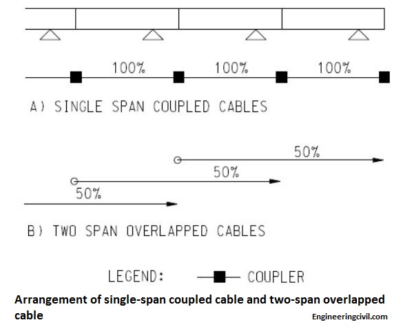
This question is taken from book named – A Closer Look at Prevailing Civil Engineering Practice – What, Why and How by Vincent T. H. CHU.
(i) Stressing all tendons in one span is time consuming. Moreover, the construction team has to wait until the concrete has gained enough strength before all tendons in the span to be stressed.
(ii) Extra time is required for coupling of tendons.
(iii) The accommodation of coupler requires the lowering of designed tendon profile. Moreover, the coupler occupies large space in bridge web which is the region of high shear forces. To avoid generating a weak point in web, the web has to be locally thickened to maintain sufficient thickness of concrete.
(iv) Couplers have a higher risk of failure when compared with normal anchorages. The success of such prestress layout is highly dependent on the quality of coupler and workmanship because coupling of all prestressing tendons is carried out at the same point.
(v) The tendon length is only one span long which is economically undesirable.
For two-span overlapped cable, the cable is two-span long. At each construction phase in span-by-span construction, only 50% of tendons are stressed. In most cases, 50% tendons stressing would be sufficient to carry its self weight upon removal of falsework. As such, it allows the use of more economically longer cable with a reduction in construction time.
This question is taken from book named – A Closer Look at Prevailing Civil Engineering Practice – What, Why and How by Vincent T. H. CHU.
What is the significance of null point in bridge deck?
What is the difference between dry joint and wet joint in precast segmental bridges?
Dry joints have been properly used in the past in which the bridge segments are formed by match casting. The prevalence in the past is due to it lower cost and time for construction. There is no gluing material to seal up the joint. As such, leakage through the joint into the box culvert occurs from time to time and this may affect the durability of external post-tensioning tendons. Moreover, owing to the effect of seismic,
temperature and creep, the joints are found to open under these conditions. Spalling of top concrete slab at bridge joint was also reported.
Wet joint involves the use of epoxy glue at the mating precast segments. After the application of epoxy glue, a temporary precompression pressure of 0.3MPa is applied by stress bars at top, bottom and the sides of the mating precast segments. The epoxy sets under the applied pressure. The use of epoxy joints provides lubrication to help in the fit-up and alignment of the mating segments and minimizes the effect of hard point contact between segments.
This question is taken from book named – A Closer Look at Prevailing Civil Engineering Practice – What, Why and How by Vincent T. H. CHU.
In precast segmental box girder bridges, the bridge segments are usually formed by match casting. It is sometimes observed that a gap is formed between adjacent bridge segments. Why?
To enhance perfect fitting of bridge segments in precast segmental box girder bridges, segments are usually constructed by match casting so that it would not impair the serviceability and load bearing ability of the bridge. The end face of completed segment is adopted as formwork for the new segment. During the concrete hardening process, the hydration effect of new segment induces a temperature rise and develops a temperature gradient in the completed segment. Hence, the completed segment bows temporarily and the new segment sticks to this bowed shape when hardened. After match casting, the completed segment retains its original shape after cooling down while the new segment obtains the profile of bowed shape. Such bowing effect is even more significant for slender segments with large height to width ratio.
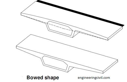
This question is taken from book named – A Closer Look at Prevailing Civil Engineering Practice – What, Why and How by Vincent T. H. CHU.
This question is taken from book named – A Closer Look at Prevailing Civil Engineering Practice – What, Why and How by Vincent T. H. CHU.
What are the main design considerations for temporary nose in incremental launching?
There are two main design considerations for temporary nose:
(i) Maximum sagging moment
The maximum sagging moment at the point of connecting the nose to superstructure occurs when the superstructure is launched far from the pier. It is estimated to occur at about 75% of the span length.
(ii) Maximum bearing pressure at bottom flange of temporary nose
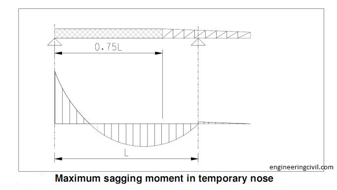
This question is taken from book named – A Closer Look at Prevailing Civil Engineering Practice – What, Why and How by Vincent T. H. CHU.
(i) Maximum sagging moment
The maximum sagging moment at the point of connecting the nose to superstructure occurs when the superstructure is launched far from the pier. It is estimated to occur at about 75% of the span length.
(ii) Maximum bearing pressure at bottom flange of temporary nose
This question is taken from book named – A Closer Look at Prevailing Civil Engineering Practice – What, Why and How by Vincent T. H. CHU.
Which of the following methods to reduce cantilever moment is better in incremental launching, (i) temporary nose, (ii) mast or (iii) auxiliary piers?
The use of mast is an alternative to temporary nose. From practical point of view, the use of mast requires continual adjustment of forces in the guys when the superstructure is pushed forward. On the other hand, the implementation of temporary nose system does not require much attention during operation.
For large span lengths (>50m) it is advantageous to adopt auxiliary piers because this helps reduce the central prestress required. However, it may not be economical for auxiliary piers with height more than 40m.
This question is taken from book named – A Closer Look at Prevailing Civil Engineering Practice – What, Why and How by Vincent T. H. CHU.
Can the use of temporary nose in incremental launching method reduce the cantilever moment of superstructure to the value of inner support moment?
When the superstructure is pushed forward, a temporary nose is usually adopted at the front end of the superstructure to reduce the cantilever moment for which the central prestress is designed. The length of
temporary nose is about 60-65% of bridge span.
The bending moment of self-weight for internal spans (equal span) of long bridge is -0.0833WL2
at piers and +0.0417W L2 at mid-span (W = unit weight of deck and L = span length). However, without the use of temporary nose, the bending moment in the leading pier when the deck has to cantilever from one pier to another would be -0.5WL2, which is 6 times higher than normal values at support.
Theoretically speaking, it is possible to reduce the cantilever moment to the value of inner support moment (i.e. -0.0833WL2) with the use of a long nose. However, from economic point of view, it is would better to adopt temporary additional prestressing instead of longer nose. Hence, in actual site practice, the use of temporary nose would not reduce the cantilever moment of superstructure to the value of inner support moment but only to achieve -0.105WL2.
Should special design be catered for in bridge piers upon jacking up of superstructure for installation of bearings in Incremental Launching method?
After the completion of launching process, the superstructure has to be lifted up to allow for installation of bearings. This is usually achieved by means of jacks to raise 5-10mm successively at each pier. In fact, it is anticipated that no special design is necessary for this operation because the effect of differential settlements at support should already be checked in bridge design. Level readings should be checked to ensure that it does not deviate from the designed figure.
This question is taken from book named – A Closer Look at Prevailing Civil Engineering Practice – What, Why and How by Vincent T. H. CHU.
This question is taken from book named – A Closer Look at Prevailing Civil Engineering Practice – What, Why and How by Vincent T. H. CHU.
Central prestressing is normally required during construction in Incremental Launching method. Why?
The erection condition plays an important role to the structural design of bridges when incremental launching method is adopted.
Each section of superstructure is manufactured directly against the
preceding one and after concrete hardens, the whole structure is moved forward by the length of one section. When the superstructure is launched at prefabrication area behind one of the abutments, it is continually subjected to alternating bending moments. Each section of superstructure (about 15m to 25m long) is pushed from a region of positive moment and then to a region of negative moment and this loading cycled is repeated. As such, tensile stresses occur alternately at the bottom and top portion of superstructure section. For steel, it is of equal strength in both compression and tension and it has no difficulty in handling such alternating stress during launching process. However concrete could only resist small tensile stresses and therefore, central prestressing is carried out to reduce the tensile stress to acceptable levels.
Central prestressing means that the prestressing cables are arranged such that the resultant compressive stresses at all points in a given cross section are equal and it does not matter whether tensile stresses occur in upper or lower portion of superstructure during launching process.
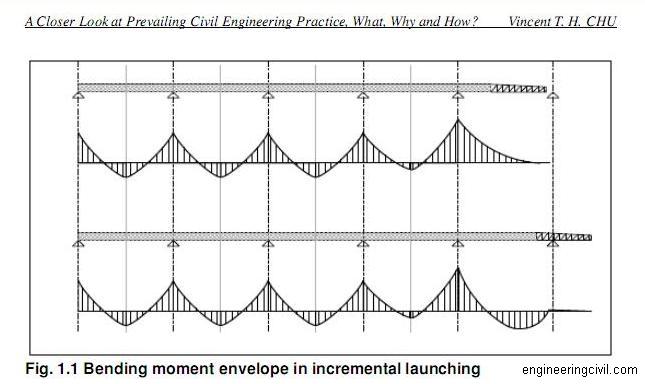
This question is taken from book named – A Closer Look at Prevailing Civil Engineering Practice – What, Why and How by Vincent T. H. CHU.
Each section of superstructure is manufactured directly against the
preceding one and after concrete hardens, the whole structure is moved forward by the length of one section. When the superstructure is launched at prefabrication area behind one of the abutments, it is continually subjected to alternating bending moments. Each section of superstructure (about 15m to 25m long) is pushed from a region of positive moment and then to a region of negative moment and this loading cycled is repeated. As such, tensile stresses occur alternately at the bottom and top portion of superstructure section. For steel, it is of equal strength in both compression and tension and it has no difficulty in handling such alternating stress during launching process. However concrete could only resist small tensile stresses and therefore, central prestressing is carried out to reduce the tensile stress to acceptable levels.
Central prestressing means that the prestressing cables are arranged such that the resultant compressive stresses at all points in a given cross section are equal and it does not matter whether tensile stresses occur in upper or lower portion of superstructure during launching process.
This question is taken from book named – A Closer Look at Prevailing Civil Engineering Practice – What, Why and How by Vincent T. H. CHU.
What is the purpose of leveling pad in bridge bearing?
Bridge bearings should be installed to lie horizontally on bridge piers and columns so that it would not induce eccentricity forces on substructure. However, the bridge superstructure requires different longitudinal and transverse level and gradient in order to keep in line with the geometry of the road. As such, it is natural to follow that the superstructure can hardly meet with substructure horizontally so that a leveling pad is introduced at the bottom of the superstructure to join with bridge bearing. Wedge-shaped leveling pad is commonly used for better concrete mobility at the bridge bearings.
This question is taken from book named – A Closer Look at Prevailing Civil Engineering Practice – What, Why and How by Vincent T. H. CHU.
This question is taken from book named – A Closer Look at Prevailing Civil Engineering Practice – What, Why and How by Vincent T. H. CHU.
Informtaive and helpful blog. We also Develop one of the best engineering perform 3d software.Keep Sharing such helpful content.
ReplyDelete