What is immersed tube method for underwater crossings?
The immersed tube method for underwater crossing involves the following basic construction steps:
(i) Prefabricating long tunnel units (steel shell or concrete) in a dry-dock or shipyard
(ii) Floating and towing the units with removable bulkhead to the site
(iii) Immerse the units in a pre-dredged trench
(iv) Connect the units one by one
(v) Covering the completed tunnel with backfill
Steel immersed tunnel is sometimes adopted because of the ease of fabrication and its relative lightness. Moreover, shorter construction time is required when compared with concrete immersed tubes.
This question is taken from book named – A Self Learning Manual – Mastering Different Fields of Civil Engineering Works (VC-Q-A-Method) by Vincent T. H. CHU.
How does the direction of approaching velocities of ships affect berthing?
One of the major effects of angle of approaching velocities of ships is its influence of the energy to be absorbed by the fender system. Consider several ships berth on the same pier at the same speed but with different angle of approach, though their kinetic energies are the same, the amount of energy absorbed by fender differs. The amount of energy absorbed by fender is :
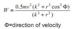
where W= energy absorbed by the fender
m= mass of the ship
v=velocity of the ship
k= radius of gyration of the ship
r= distance of centre of gravity of the ship to the point of contact of the fender
Hence, when the direction of approaching velocity of a ship is normal to the fender system (i.e. phi=90 ), the amount of energy absorbed is smaller when compared with that of a ship whose velocity is tangential to the shoreline.
This question is taken from book named – A Self Learning Manual – Mastering Different Fields of Civil Engineering Works (VC-Q-A-Method) by Vincent T. H. CHU.
What is the design level of landings in piers?
Landings are designed as resting place for passengers during berthing and deberthing of vessels. In general, landings are provided near mean high and mean low water levels to facilitate embarking and disembarking of passengers (BS6349: Part 2: 1988). Therefore, the level of landing steps should be different from place to place because of different mean high and mean low water levels in different locations.
This question is taken from book named – A Self Learning Manual – Mastering Different Fields of Civil Engineering Works (VC-Q-A-Method) by Vincent T. H. CHU.
This question is taken from book named – A Self Learning Manual – Mastering Different Fields of Civil Engineering Works (VC-Q-A-Method) by Vincent T. H. CHU.
Should the Morison equation or diffraction analysis be adopted in determining wave force on piles?
The choice between the Morison’s equation and diffraction analysis in determining the wave forces on piles depends on the ratio between the diameters of piles to wavelength. If the ratio between the diameter of piles to wavelength is less than 0.2, the Morison equation is usually
recommended. The reason behind this is that the effect of viscosity and separation is significant below this ratio. On the contrary, if the ratio between the diameter of piles to wavelength exceeds 0.2, the waves are scattered with negligible occurrence of separation. As such, diffraction analysis is adopted to calculate the wave forces on piles
This question is taken from book named – A Self Learning Manual – Mastering Different Fields of Civil Engineering Works (VC-Q-A-Method) by Vincent T. H. CHU.
Hudson’s formula and Van der Meer formula are commonly used in the design of armour. Which one is a better choice?
Hudson’s formula is commonly adopted in preliminary design to obtain rough initial estimate of rock size. The formula is derived from the results of regular wave tests. However, this formula does not take into account the following elements which Van der Meer formula does: wave period, damage level, permeability of structure and storm duration. Moreover, Hudson’s formula deals with the use of regular waves only.
Compared with Hudson’s formula, Van der Meer formula is more complicated and it is derived from results of a series of physical model tests. They include the consideration of wave period, storm duration, clearly-defined damage level and permeability of structure. The choice of the appropriate formula is dependent on the design purpose (i.e. preliminary design or detailed design).
Compared with Hudson’s formula, Van der Meer formula is more complicated and it is derived from results of a series of physical model tests. They include the consideration of wave period, storm duration, clearly-defined damage level and permeability of structure. The choice of the appropriate formula is dependent on the design purpose (i.e. preliminary design or detailed design).
What are the factors determining the stability of a single armour unit?
There are mainly three main factors which govern the stability of a armour unit, namely, gravity, intertangling and squeezing. Obviously, it is beyond doubt that the ability of the armour unit to stay in place should be closely related to gravity force. On the other hand, the geometry of the armour unit also affects its stability. For instance, with the difference in ability to intertangle, their resistance to pulling out by waves varies. Furthermore, squeezing forces by gravity also affects the stability of the armour unit which is dependent on frictional forces in all directions.
This question is taken from book named – A Self Learning Manual – Mastering Different Fields of Civil Engineering Works (VC-Q-A-Method) by Vincent T. H. CHU.
This question is taken from book named – A Self Learning Manual – Mastering Different Fields of Civil Engineering Works (VC-Q-A-Method) by Vincent T. H. CHU.
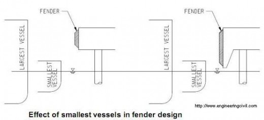
Should small vessels be considered in the design of fenders?
Smallest vessel should also be taken into consideration when designing fender system. In vertical orientation of fender system, the types and sizes of all vessels should be considered taking into account the tidal effect at that region. To conduct proper design of fender system, engineers must consider the height and draft of both the smallest and largest vessels to determine the point of contact on the fender. It is not uncommon that design of fender system considers only the largest vessels berthing in the pier which should be avoided as it might not function for smaller vessels berthing in dock.
This question is taken from book named – A Self Learning Manual – Mastering Different Fields of Civil Engineering Works (VC-Q-A-Method) by Vincent T. H. CHU.
This question is taken from book named – A Self Learning Manual – Mastering Different Fields of Civil Engineering Works (VC-Q-A-Method) by Vincent T. H. CHU.
Should stiff or soft fenders be designed for berthing in piers?
The elasticity of fenders is related to the ability to release the stored energy during berthing of vessels. However, it has no effect on the reaction force and the deflection of fender system. The amount of energy that a fender can absorb is dependent on the reaction-deflection curve and is represented by the area under the curve. The higher is the reaction force, the higher amount of energy would be absorbed by the fender provided that the resistance of ships’ hull is sufficient to withstand the force without permanent deformations. Although stiff and soft fender may have the same deflection under the same maximum reaction force acting on the berthing vessel, the amount of energy absorbed by stiff fenders is much higher than that of soft fenders. Consequently, stiff fenders should be employed for berthing purpose.
On the other hand, in mooring operations where vessels are constantly subject to wave action, it is desirable to keep the tension force on the rope to a low value. In this connection, it is recommended to use soft fenders.
This question is taken from book named – A Self Learning Manual – Mastering Different Fields of Civil Engineering Works (VC-Q-A-Method) by Vincent T. H. CHU.
Can water help dissipate part of berthing energy?
Depending on the configuration of pier, water could help dissipate part of berthing energy. For instance, for closed docks in which there is a solid wall going down directly to the bottom of seabed, the quay wall will push back all the water that is being moved by the vessel and creates a cushion effect which dissipates part of berthing energy (10-20%). On the contrary, for open dock in with piles beneath and water can flow through the underside of piers, there shall be no cushion effect of water.
Similarly, the larger is the draft of vessels, the less trapped water can escape under the vessel so that the cushion effect of water can be enhanced to dissipate part of berthing energy.
This question is taken from book named – A Self Learning Manual – Mastering Different Fields of Civil Engineering Works (VC-Q-A-Method) by Vincent T. H. CHU.
Why do vessel operators choose to contact the fender system at its bow instead of mid-ship location during berthing operation?
When calculating berthing energy of vessels, there is a factor called “eccentricity factor” which accounts for different berthing energy when the vessel contact the fender system at different locations of the vessel.
For instance, for mid-point berthing the eccentricity factor is unity which means there is no loss of berthing energy. For third-point berthing and quarter-point berthing, the eccentricity factor is 0.7 and 0.5 respectively. In fact, engineers always attempt to reduce the amount of berthing energy to be absorbed by fender system and pier structures. As such, it is recommended for vessels to contact fender system at its bow or stern because the reaction force would produce a rotational moment to the vessel which dissipates part of vessel’s energy.
For instance, for mid-point berthing the eccentricity factor is unity which means there is no loss of berthing energy. For third-point berthing and quarter-point berthing, the eccentricity factor is 0.7 and 0.5 respectively. In fact, engineers always attempt to reduce the amount of berthing energy to be absorbed by fender system and pier structures. As such, it is recommended for vessels to contact fender system at its bow or stern because the reaction force would produce a rotational moment to the vessel which dissipates part of vessel’s energy.
In fender design, when calculating the berthing energy absorbed by fenders, should engineers take into account energy absorbed by piers?
The design of a fender system is based on the principle of conservation of energy. The amount of energy brought about by berthing vessels into the system must be determined, and then the fender system is devised to absorb the energy within the force and stress limitations of the ship’s hull, the fender, and the pier.
Firstly, the energy released by the largest/heaviest vessel allowed to use on the pier is determined to be delivered to the pier by first impact. Then, the energy that can be absorbed by the pier would be calculated. For pier structures that are linearly elastic, the energy is one-half the maximum static load times the amount of deflection. However, in case the structure is extremely rigid, it can be assumed to absorb no energy.
The energy to be absorbed by fender system should be the total energy of berthing vessels deducting the energy absorption by pier structures. Finally, a fender system capable of absorbing the amount of energy without exceeding the maximum allowable force in the pier should be chosen from fender product catalogue.
This question is taken from book named – A Self Learning Manual – Mastering Different Fields of Civil Engineering Works (VC-Q-A-Method) by Vincent T. H. CHU.
For underwater concreting, tremie pipes are normally used with the aid of hoppers. Sometimes tubes are inserted inside the hoppers. Why?
In placing concrete by tremie pipes, hoppers are connected to their top for receiving freshly placed concrete. However, air may be trapped inside the tremie pipes if there is rapid feeding of fresh concrete. To release the trapped air inside the tremie pipes, hoses (called ventilation tubes) are inserted and lowered down through the hoppers. Reference is made to Carl A. Thoresen (1988).
This question is taken from book named – A Self Learning Manual – Mastering Different Fields of Civil Engineering Works (VC-Q-A-Method) by Vincent T. H. CHU.
This question is taken from book named – A Self Learning Manual – Mastering Different Fields of Civil Engineering Works (VC-Q-A-Method) by Vincent T. H. CHU.
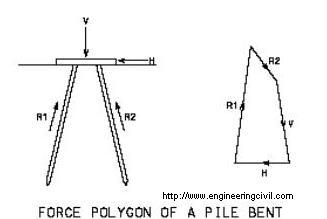
For typical pile bents in marine piers, how is vertical loads related to horizontal capacity of the pile bents?
Let’s consider a pile bent with a top slab supported by two ranking piles, each inclining at an equal angle to the pier slab. In designing such a system, truss action is normally adopted to analyze the pile bent. When the reaction forces of these piles, horizontal forces (e.g. due to berthing and deberthing of vessels) and vertical forces (e.g. superimposed deck loads) are analyzed by drawing a force polygon, it is noted that lateral resistance of the pile bent is dependent on the vertical load, i.e. lateral resistance is small when vertical loads are high.
This question is taken from book named – A Self Learning Manual – Mastering Different Fields of Civil Engineering Works (VC-Q-A-Method) by Vincent T. H. CHU.
This question is taken from book named – A Self Learning Manual – Mastering Different Fields of Civil Engineering Works (VC-Q-A-Method) by Vincent T. H. CHU.
Why “inadequate pile founding level” commonly occurs in piles of piers?
The most severe load on piers generally is the horizontal load due to berthing and mooring of large vessels. The design of piers is taken as an example to illustrate the importance of adequate pile founding level. Since the widths of open berth piers are relatively small so that they provide a short lever arm to counteract the moment induced by berthing loads. Moreover, the dead load of open berth piers are normally quite light and therefore the resisting moment provided by the dead load of pier structures may not be sufficient to counteract the moment generated by berthing loads. To aid in providing adequate resistance to the overturning moment by the berthing load, the soil resistance above bedrock contributes to the stabilizing moment. For commonly adopted marine piling type, i.e. driven steel tubular piles with reinforced concrete infill, driven piles can at most be founded on top of rockhead surface. In case the rockhead level is shallow (e.g. near shoreline), the little soil cover may result in inadequate lateral resistance to the berthing load.
This question is taken from book named – A Self Learning Manual – Mastering Different Fields of Civil Engineering Works (VC-Q-A-Method) by Vincent T. H. CHU.
This question is taken from book named – A Self Learning Manual – Mastering Different Fields of Civil Engineering Works (VC-Q-A-Method) by Vincent T. H. CHU.
Can soil plug be removed in marine piling system of steel tubular pile with reinforced concrete infill?
During initial driving process, open-ended steel piles are driven through the soils at their bases. However, shaft friction will gradually develop between the steel piles and soils inside piles at some time after pile driving. The hitting action of driving hammers induces forces to the soil and later it comes to a stage when the inertial forces of inside soils, together with the internal frictional forces exceeds the bearing capacity of soils at pile toes. Consequently, the soil plug formed is brought down by the piles.
It is practically possible to excavate all soils inside steel tubular piles and replace them completely by reinforced concrete. However, as engineers strive to produce economical design the extra cost associated with excavation of soil plug and filling of concrete could be saved in case the soil plug remains in position. Moreover, from the technical point of view it is considered unnecessary to remove the soil plugs because it serves to provide a platform for the placing of on-top infill concrete on one hand and to fill the void space below the infill concrete on the other hand. In addition, the soil plug is considered to be sufficiently compacted by pile driving action and is deemed to be stable during the design life of the piling system.
It is practically possible to excavate all soils inside steel tubular piles and replace them completely by reinforced concrete. However, as engineers strive to produce economical design the extra cost associated with excavation of soil plug and filling of concrete could be saved in case the soil plug remains in position. Moreover, from the technical point of view it is considered unnecessary to remove the soil plugs because it serves to provide a platform for the placing of on-top infill concrete on one hand and to fill the void space below the infill concrete on the other hand. In addition, the soil plug is considered to be sufficiently compacted by pile driving action and is deemed to be stable during the design life of the piling system.
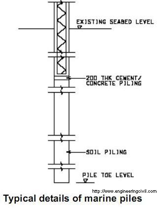
What is the significance of reinforced concrete infill in marine piling system of steel tubular pile with reinforced concrete infill?
Reinforced concrete is designed to fill the void space inside the steel tubular piles from pile cap to a certain distance below seabed. As mentioned earlier, steel tubular piles above seabed level is assumed in design to be completely corroded when approaching the end of design life. As such, loads from pile caps are transferred directly to reinforced concrete infill instead of steel tubular piles. The load transfer path below seabed level is as follows: loads from reinforced concrete infill are transferred to steel tubular piles through frictional force between reinforced concrete infill and steel piles. Therefore, mobilization of frictional forces between reinforced concrete infill and steel piles is essential to ensure that the piling system functions properly.
This question is taken from book named – A Self Learning Manual – Mastering Different Fields of Civil Engineering Works (VC-Q-A-Method) by Vincent T. H. CHU.
This question is taken from book named – A Self Learning Manual – Mastering Different Fields of Civil Engineering Works (VC-Q-A-Method) by Vincent T. H. CHU.
Why are sleeves often installed inside the lower part of open-ended driven piles?
In marine piles, open-ended piles are more often used than close-ended piles to enhance longer length of piles installed. This is essential to provide better lateral resistance against berthing loads and other lateral loads in marine structures.
To enhance longer length of driven piles installed, sleeves can be employed inside the lower part of open-ended driven piles. The sleeves lead to improved drivability with more soil entering the pile to from soil plug. The longer is the sleeves, the higher is the plugged length. This is because there is higher stress release experienced by soils flowing past the sleeves.
This question is taken from book named – A Self Learning Manual – Mastering Different Fields of Civil Engineering Works (VC-Q-A-Method) by Vincent T. H. CHU.
How does soil plug in open-ended tubular piles affect its loading carrying capacity?
In marine piles, the tubular piles are sometimes purposely designed to be open-ended to facilitate deeper penetration. In this mode of pile formation, soil plug is formed inside the piles.
The plugging ratio (the ratio of length of soil plug to the length of pile penetration) affects the load carrying capacity of piles. It was demonstrated by experiments that the end bearing capacity decreases with an increase in the plugging ratio. Moreover, close-ended piles display a higher end bearing capacity than open-ended piles as close-ended piles prevent soil from entering the piles and force them around the pile tip leading to a higher stress state in this region.
This question is taken from book named – A Self Learning Manual – Mastering Different Fields of Civil Engineering Works (VC-Q-A-Method) by Vincent T. H. CHU.
What is the mechanism of formation of soil plugs in marine driven steel piles with reinforced concrete infill?
During initial driving process, open-ended steel piles are driven through the soils at their bases. However, shaft friction will gradually develop between the steel piles and soils inside piles at some time after pile driving. The hitting action of driving hammers induces forces to the soil and later it comes to a stage when the inertial forces of inside soils, together with the internal frictional forces exceeding the bearing capacity of soils at pile toes. Consequently, the soil plug formed is brought down by the piles. Reference is made to M. J. Tomlinson (1977).
Note: A soil plug is a column of soil formed at the bottom portion of marine pile type of steel tubular piles with reinforced concrete infill.
This question is taken from book named – A Self Learning Manual – Mastering Different Fields of Civil Engineering Works (VC-Q-A-Method) by Vincent T. H. CHU.
Why are steel tubular marine piles often driven open-ended?
In marine structures where piles are constantly subject to significant lateral and uplift forces induced by berthing operation and wave action, it is necessary to drive the piles to much greater depth. To avoid premature refusal so that insufficient soil cover may develop which is incapable of providing the required lateral and uplift resistance, tubular piles are normally driven open-ended so that they are driving to greater depths than piles with closed ends.
What is the problem in traditional marine piling system of steel tubular pile with concrete infill and what are the possible remedial measures?
In the design of marine piles of steel tubular piles with concrete infill, loads from pier deck are taken up by steel tubular piles before the occurrence of corrosion of steel piles above seabed. In fact, it is assumed that steel piles above seabed level will all be corroded after a certain year. The load transfer mechanism after complete corrosion of steel pile above seabed is as follows: loads from pier deck are taken up by concrete infill above the seabed level. Below the seabed level, loads would be transferred to steel piles through frictional forces between concrete infill and steel casings.
However, substantial radial shrinkage and contraction occurs after concreting of concrete infill and this will hinder the load transfer from the concrete infill to steel piles because the bond may be ruptured by radial shrinkage. It is in doubt if frictional forces can be properly developed in this situation. To solve this problem, shear keys could be installed at regular spacing inside steel piles to ensure their rigid connection with concrete infill. Alternatively, expanding agents may be adopted in concrete mixes to ensure that there is no shrinkage after the concreting process.
This question is taken from book named – A Self Learning Manual – Mastering Different Fields of Civil Engineering Works (VC-Q-A-Method) by Vincent T. H. CHU.
For marine pile type of steel tubular piles with reinforced concrete infill, minimum toe level is often specified in contract drawings. What is its purpose?
The purpose of minimum toe level is two-fold:
(i) In detailed design stage, ground investigation should be conducted and the approximate level of rockhead is known. Therefore, to avoid the marine piles to be founded prematurely on boulders, minimum toe levels of marine driven piles are specified in contract.
(ii) It provides sufficient length of soils for lateral and uplift resistance.
Note: Minimum toe level refers to the minimum level that a marine driven pile should be driven into seabed.
This question is taken from book named – A Self Learning Manual – Mastering Different Fields of Civil Engineering Works (VC-Q-A-Method) by Vincent T. H. CHU.
F
Why are most marine piles circular in cross section?
For marine piles, there are several options available for selection, namely H-piles, circular pipes and box piles.
However, only circular piles and box piles are suitable for marine application because of the following two reasons suggested by G. M. Cornfield (1968):
(i) Circular piles and box piles possess high column buckling strength. For marine structures like jetties, piles are well above seabed level and therefore the column buckling effect is significant when compared with other structures. Therefore, it is essential to use pile sections which have relatively high buckling strength in piers.
(ii) Circular piles and box piles display high energy absorbing capability. For marine structures like dolphins and fenders, which require substantial amount of berthing energy to be absorbed, these piles sections are inevitably good choices.
In marine structures, it appears that circular sections prevail over the box sections. The main reason is that the range of section available for selection of circular piles is more than that of box piles.
This question is taken from book named – A Self Learning Manual – Mastering Different Fields of Civil Engineering Works (VC-Q-A-Method) by Vincent T. H. CHU.
What are the functions of slip joints in blockwork seawalls?
Slip joints are joints which are formed through a complete vertical plane from the cope level to the toe level of seawalls. These joints are designed in blockwork seawalls to cater for possible differential settlements between adjacent panels of seawalls. The aggregates inside the half-round channels in slip joints allow for the vertical movements induced by differential settlement and at the same time providing aggregate interlocking forces among adjacent panels of seawalls to link the panels in one unit against the lateral earth pressure exerted on seawall.
Besides, slip joints provide a path for the relief of water pressure developed and allow the lateral movement (e.g. contraction) due to seasonal variations.
Note: For details of slip joints, reference is made to CEDD Standard Drawing No. C3008C.
This question is taken from book named – A Self Learning Manual – Mastering Different Fields of Civil Engineering Works (VC-Q-A-Method) by Vincent T. H. CHU.
In case a road passes through a reclaimed land and an existing land, what is the main concern regarding the design of pavements?
For an existing land, it is anticipated that there will be no major settlement within the design life of pavement structures. However, for a recently reclaimed land, even with surcharging and installation of vertical drains, some settlement will still occur after the construction. If a road pavement has to be constructed connecting these two areas, special design has to be made in this transition region. In order to avoid the occurrence of differential settlement which may damage the pavement structure, a transition slab may be designed to accommodate such movement (J. S. M. Kwong (1996).
Geotechnical Instrumentation is frequently employed for monitoring the condition of reclamation. Sometimes two piezometers are installed inside the same borehole. What is the reason behind this?
For standpipes, they normally contain one plastic tube between its intention is to measure water level only. However, for piezometers, they are used for measuring pore water pressure in a certain depth below ground. For instance, if there are two clayey layers below ground at different depths, a multiple piezometer including two separate piezometers may be sunk at the same borehole to determine the pore water pressure at these layers respectively. This arrangement has the advantage that it saves the cost of installation of separate boreholes for several piezometers. However, the installation of multiple piezometers within the same borehole is affected by occurrence of leakage along the pipes as suggested by Marius Tremblay (1989).
This question is taken from book named – A Self Learning Manual – Mastering Different Fields of Civil Engineering Works (VC-Q-A-Method) by Vincent T. H. CHU.
This question is taken from book named – A Self Learning Manual – Mastering Different Fields of Civil Engineering Works (VC-Q-A-Method) by Vincent T. H. CHU.
Why can vacuum preloading be employed to accelerate the rate of consolidation?
In vacuum preloading, the drainage boundary of clay is isolated from the atmosphere by a membrane. A partial vacuum (e.g. suction of 80kPa) is applied within the membrane to reduce the water pressure so as to speed up consolidation.
The rate of consolidation can be increased by surcharge preloading in which the excess pore water pressure in clay is temporarily increased. Alternatively, the rate of consolidation can also be increased by vacuum preloading by a decrease in water pressure.
Vacuum preloading is generally faster in operation than surcharge preloading which requires timely delivery of fill on top of clay. Moreover, it is unnecessary to consider the stability criterion which surcharge preloading should require.
This question is taken from book named – A Self Learning Manual – Mastering Different Fields of Civil Engineering Works (VC-Q-A-Method) by Vincent T. H. CHU.
How does overflowing in trailing suction hopper dredger affect the water regime?
Trailing suction hopper dredger contains a large hopper for storage and transport of dredged materials. The dredging operation is implemented by a hydraulic dredging system including draghead, suction pip, pumps for taking up the material from seabed and putting them into the hopper.
When dredging materials, overflowing may occur to increase the solid loads in the hopper and improve the efficiency of dredging operation. The removal of excess water and soil/water mixture with low density enhances the storage of soils mixture with higher density. Hence, this lowers the cost of dredging by increasing the rate of production. If no overflow is allowed during the dredging operation, trailing suction hopper dredger can normally carry about 10% of normal load and this essentially increases the cost of dredging operation.
If overflowing is allowed in the dredging operation, it shall work on unrestricted basis as the rate of overflow is nearly constant over the entire overflowing process. For dredging with overflowing, the particle size distribution of sand may differ from the in-situ grading because overflowing tends to remove the fine content of sand.
The loss of sediment associated with overflowing poses environmental problems to the nearby water zone in the following ways:
(i) increased sedimentation
(ii) decrease in dissolved oxygen
(iii) increased turbidity
(iv) increased amount of nutrients
This question is taken from book named – A Self Learning Manual – Mastering Different Fields of Civil Engineering Works (VC-Q-A-Method) by Vincent T. H. CHU.
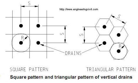
Vertical drains can be installed in square and triangular patterns. Which pattern is better?
Vertical drains are commonly installed in square and triangular patterns. The zone of influence of vertical drains (R) is a function of drain spacing (S).
For drains in square pattern: R = 0.546S
For drains in triangular pattern: R = 0.525S
The advantages of square pattern are that it is more convenient to lay out and manage on site. However, triangular pattern is the most popular one because it provides a more uniform consolidation between drains than square pattern.
This question is taken from book named – A Self Learning Manual – Mastering Different Fields of Civil Engineering Works (VC-Q-A-Method) by Vincent T. H. CHU.
What is the purpose of providing shoes in prefabricated drains?
Shoes are normally installed in prefabricated drains for the following reasons:
(i) It avoids the entry of soils into the mandrel by sealing it during the installation of drains.
(ii) It performs like an anchor to retain the drains at the designed depth and to stop the drains from being pulled out during the withdrawn of mandrels after driving the mandrels into ground.
However, the inclusion of shoes in prefabricated drains tends to aggravate the problem of smear effect because the shoes are usually larger in size than mandrels.
What are the considerations in selecting marine plants and land plants for installation of band drains?
For installation of band drains by marine plants, it must have sufficient water depth to accommodate the marine plants in the first place. However, due to the effect of tides and waves, the establishment of the position for installation of band drains and the subsequent installation works may be affected. In addition, the establishment cost of marine plants is higher than that of land plants.
For installation of band drains by land plants, difficulty may be encountered during the installation of band drains through the reclaimed layer e.g. C&D material. Land plants may take longer construction time due to the above-mentioned difficulty. Sometimes when the supply of public fill is increased suddenly, it may be preferable to place these fill immediately into position and in this situation the installation of band drains (originally installed by marine plants) is delayed so that the construction of band drains is changed to using land plants.
This question is taken from book named – A Self Learning Manual – Mastering Different Fields of Civil Engineering Works (VC-Q-A-Method) by Vincent T. H. CHU.
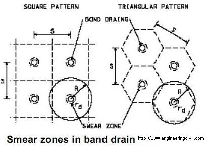
For drained reclamation, what is the significance of smear zone induced by installation of band drains?
During installation of band drains, smear zones are created in which a zone of soil surrounding the band drains are disturbed. The compressibility of surrounding soils is increased and it results in the reduction of their permeability. In fact, the surrounding soils are remoulded during the installation process and the effectiveness of band drains is reduced. In essence, for the reduced permeability of soils around band drains, it takes longer time to complete the consolidation process.
This question is taken from book named – A Self Learning Manual – Mastering Different Fields of Civil Engineering Works (VC-Q-A-Method) by Vincent T. H. CHU.
This question is taken from book named – A Self Learning Manual – Mastering Different Fields of Civil Engineering Works (VC-Q-A-Method) by Vincent T. H. CHU.
What are the potential problems of smear around vertical drains?
Smear zones are generated during the installation of vertical drains in which the zone of soils surrounding the band drains are disturbed. Soils in the smear zones are remoulded during the installation process and the effectiveness of band drains is reduced. For instance, the compressibility of surrounding soils is increased and this brings about the reduction of their permeability. In essence, with the reduced permeability of soils around band drains, it takes longer time to complete the consolidation process.
To prevent the formation of smear zones, the raising and lowering of mandrel during drain installation should be minimized. Moreover, soil disturbance can be controlled by avoiding the use of vibratory hammers which serve to drive the drains into the ground.
This question is taken from book named – A Self Learning Manual – Mastering Different Fields of Civil Engineering Works (VC-Q-A-Method) by Vincent T. H. CHU.
Why do prefabricated band drains become more popular than sand drains?
There is a trend that sand drains are replaced by prefabricated band drains due to:
(i) The rate of installation of prefabricated band drains is high. As such, substantial cost and time could be saved by using this method of
construction.
(ii) The disturbance of soil during installation of drains is smaller when using prefabricated band drains.
(iii) The ease of fabrication, quality control and storage associated with band drains.
This question is taken from book named – A Self Learning Manual – Mastering Different Fields of Civil Engineering Works (VC-Q-A-Method) by Vincent T. H. CHU.
For reclamation by hydraulic filling with sand, it is commonly observed that the density of sand varies significant with depth. Why?
In reclamation works, the density of filled sand varies with the method of placement. For example, bottom dumping is adopted for sand as the method of placement and this results in higher density of filled sand. For placement by pipeline discharge, the density of filled sand formed by this method is lower than that by bottom dumping. Hence a weak zone is formed for sands placed by pipeline discharge and hence these loose sand fill (relative density about 30%) may cause settlement when subjected to loading or vibrations.
In general, the filled sand above water table is found to be higher in density as they are well compacted by bulldozers and traffic of constructional plant.
In general, the filled sand above water table is found to be higher in density as they are well compacted by bulldozers and traffic of constructional plant.
Why do compliance test be carried out some time after the completion of vibrocompaction?
A process called “ageing” occurs after the operation of vibrocompaction. It is observed that sand fill shows an increase in strength and stiffness. Upon immediate completion of vibrocompaction, the apparent increase in strength of sand fill is due to dissipation of air and water pressure. Then the ageing process shall continue owing to creep and cementation.
Hence, sufficient time shall be established for ageing of sand fill to develop prior to compliance testing (such as CPT test). Otherwise, it may result in non-compliant strength and requires re-compaction.
This question is taken from book named – A Self Learning Manual – Mastering Different Fields of Civil Engineering Works (VC-Q-A-Method) by Vincent T. H. CHU.
Vibrocompaction is carried out to loose sand after reclamation by filling sand. How to determine the in-situ density of filled sand?
It is difficult to obtain undisturbed samples of sand to measure the in-situ density. The relative density of in-situ sand can be determined by correlation to other parameters in some methods. For instance, Cone Penetration Test can be employed to estimate the relative density of sands as there is well established relation between cone tip resistance and relative density.
On the other hand, shear wave velocity measurements using seismic CPT and Spectral Analysis of Surface Waves can be used to obtain relative density indirectly.
This question is taken from book named – A Self Learning Manual – Mastering Different Fields of Civil Engineering Works (VC-Q-A-Method) by Vincent T. H. CHU.
Should silt curtain be designed to touch seabed?
Silt curtains are impermeable vertical barriers extending from the seawater surface to their designed depths. The curtains are held in a vertical position by the carrier float on their top and a curtain weight at their bottom. A tension cable is designed at the carrier float to resist stresses incurred by currents. Moreover, the silt curtains are anchored to the seabed to hold them in the designed configuration.
In essence, the depth of silt curtains should not be so long and touch the seabed because the bottom segment of the silt curtains would be trapped inside the newly accumulated sediment, thus resulting in the sinking of the curtain. It is difficult to remove these sunken curtains. Moreover, reversal tidal and current actions may cause movement of bottom region of curtains which stir up the settled suspensions and create additional turbidity.
This question is taken from book named – A Self Learning Manual – Mastering Different Fields of Civil Engineering Works (VC-Q-A-Method) by Vincent T. H. CHU.
Why are observed settlements in reclamation normally larger than calculated?
Settlement in reclamation area occurs as a result of primary consolidation (i.e. by dissipation of excess pore water pressure) and secondary compression which involves creep of soils. Creep of soils occurs by viscous squeezing out of absorbed water in double layers of clay particles and rearrangement of clay particles under loading.
In the calculation of settlement in reclamation, there are generally two methods available. The first method assumes that creep occurs during the process of primary consolidation, which appears to be logically correct. On the other hand, the second method assumes that creep of soils occurs after primary consolidation and hence at the end of consolidation period the calculation settlement is equal to primary consolidation only without any consideration of creep effects. This method of settlement calculation is well adopted by most consulting firms and hence leads to underestimation of total settlement.
This question is taken from book named – A Self Learning Manual – Mastering Different Fields of Civil Engineering Works (VC-Q-A-Method) by Vincent T. H. CHU.
In reclamation involving large volumes of fill and tight programme, shall engineers use marine fill or mud extracted from land borrow area as filling material?
There are two advantages of adopting marine fill over mud extracted from land borrow area:
(i) In some land borrow areas, it involves breaking up of rock to suitable sizes for reclamation and the production rate is not high. With modern equipment for dredging and placing marine fill, the filling rate is much higher.
(ii) The cost incurred for breaking up of rock to suitable sizes for reclamation is very expensive while the cost of hydraulic filling with marine fill is lower.
In reclamation by filling sand, what is the effect of filling operations below mean sea level?
Filling below mean sea level usually has a low density. The settling sand in standing water would form a loose skeleton leading to a low density. However, as the sand level is rising, the increased load causes reallocation of sand grains in lower layers. As such, after dissipation of excess pore water pressure, it results in increased density.
This question is taken from book named – A Self Learning Manual – Mastering Different Fields of Civil Engineering Works (VC-Q-A-Method) by Vincent T. H. CHU.
This question is taken from book named – A Self Learning Manual – Mastering Different Fields of Civil Engineering Works (VC-Q-A-Method) by Vincent T. H. CHU.
What is the importance of geotextiles and sand in reclamation works?
For geotextiles used in reclamation, they serve mainly the following two purposes:
(i) they separate reclamation fill from marine mud;
(ii) they may act as reinforcement to enhance the stability of reclamation.
However, the reinforcement function is still under heated debate because its performance as reinforcement depends on several factors like the directional strength of woven geotextiles and damage effect by installation of vertical band drains.
For sand:
(i) it spreads the load of future public dump on top of it;
(ii) it acts as drainage path for dissipation of excess pore water pressure for band drain installation.
This question is taken from book named – A Self Learning Manual – Mastering Different Fields of Civil Engineering Works (VC-Q-A-Method) by Vincent T. H. CHU.
In case mud waves occur during reclamation, what are the possible solutions to rectify the situation?
(i) Option 1 – Complete Removal of All Disturbed Mud
To remove all disturbed mud once mud waves occur is the fastest way to treat the problem. After that, filling material is used for replacing the disturbed mud. However, this option is a rather expensive option because it involves dredging of all disturbed mud and replacement of large amount of fill.
(ii) Option 2 – Accelerated consolidation of Disturbed Mud
This option involves placement of surcharging loads on top of mud waves, together with installation of band drains to accelerate the consolidation of disturbed mud. This method suffers from the drawback that sufficient long time is required for the consolidation process of mud.
(iii) Option 3 – Partial Removal of Disturbed Mud
This option is a combination of the first two options in which the top weak layer of mud is removed while the lower mud is treated with surcharging with band drain installation.
Note: Mud waves refer to excessive displacement of mud due to successive slip failure during reclamation.
This question is taken from book named – A Self Learning Manual – Mastering Different Fields of Civil Engineering Works (VC-Q-A-Method) by Vincent T. H. CHU.
What is the purpose of formation of bunds in reclamation?
Reclamation works normally proceed behind the seawall to protect against typhoon attack. In case where soft marine mud is encountered during reclamation, bunds may be formed on planned alignment of road and drainage works and locations of early development to displace mud to other less important areas should mudwaves indeed occur. Reclamation may be carried out in strips or even crossed bunds forming a grid. Hence, if mudwaves really occur, they could be isolated and dealt with individually.
This question is taken from book named – A Self Learning Manual – Mastering Different Fields of Civil Engineering Works (VC-Q-A-Method) by Vincent T. H. CHU.
This question is taken from book named – A Self Learning Manual – Mastering Different Fields of Civil Engineering Works (VC-Q-A-Method) by Vincent T. H. CHU.
In dredged reclamation, what are the considerations in selecting between trailer suction hopper dredgers and grab dredgers?
Trailer suction hopper dredgers are vessels which remove material off the seabed through hydraulic suction by using pumps. During the dredging operation, a mixture of soil and water is transported through suction pipe to storage hoppers. Significant turbulence inside the hoppers keeps the dredged mixture in suspension and this should be minimized to enhance the material to settle swiftly prior to the process of overflowing. Trailer suction hopper dredgers are mounted with draghead or dragarm pumps which increases the dredging depth and trims down the occurrence of cavitation as suggested by John B. Herbioh (1992). This machine is limited to dredging relatively low-strength material. Moreover, they cannot be deployed in very shallow waters and instead grab dredgers should be used. However, its dredging capacity is higher than that of grab dredger and it can be mobilized in relatively deep-water region.
Trailer suction hopper dredgers are renowned for their mobility, versatility and capability to operate in unfavorable sea conditions.
Trailer suction hopper dredgers are renowned for their mobility, versatility and capability to operate in unfavorable sea conditions.
What are different approaches for reclamation in deep water region and shallow water region?
To illustrate the different approaches adopted for reclamation in deep water and shallow water region, the following example is used:
In deepwater region, consider the seabed level is –8.5mPD. After laying of geotextiles and 1.5m thick sand blanket, the top level of sand blanket is about –7mPD. Split barges are deployed for dumping public fill to –2.5mPD. Afterwards, end dipping of public fill by trucks will be carried out up to +2.5mPD which is the designed reclamation level. Between level –2.5mPD and +2.5mPD, it is too shallow for split barges to enter the water, thus the method of end dipping is used instead.
For shallow water region, the seabed level is taken as –5.5mPD in this example. With the laying of geotextiles and 1.5m sand blanket into position, the top level of sand blanket is about –4mPD. In this case, split barges are also used for reclamation work between the level –4mPD and –2.5mPD. After that, if end dipping is used for reclamation work above –2.5mPD, then in considering the relative thin layer of fill above seabed (1.5m sand blanket + 1.5m sand blanket), it stands a high chance that mud wave would occur in seabed. Therefore, half-loaded derrick barges are employed for reclamation up to level 0mPD. With a thicker layer of public fill now, end dipping can then be used for reclamation between 0mPD and +2.5mPD.
This above reclamation sequence is just an example to demonstrate the different considerations for reclamation in deep water and shallow water region.
This question is taken from book named – A Self Learning Manual – Mastering Different Fields of Civil Engineering Works (VC-Q-A-Method) by Vincent T. H. CHU.
What are the pros and cons of using timber fenders, plastic fenders and rubber fenders?
Timber fenders:
They are low in strength and are subject to rotting and marine borer attack. Moreover, they have low energy absorption capacity and the berthing reaction depends on the point of contact. The contact pressure between fender and vessels are high. They are considered to be environmentally unfriendly because they consume tropical hardwoods in their production.
Plastic fenders:
Their strength is similar to that of timber fenders but they have relatively high abrasive resistance. They are resistant to chemical and biological attack. Their energy absorption capacities are moderate and the berthing reactions are also dependent on the point of contact. The reaction is lower when compared with timber fenders for a given energy absorption. They are considered to be environmental friendly because they are manufactured from recycled material.
Rubber fenders:
They possess high abrasive resistance and are also resistant to most biological and chemical attacks. They have moderate to high energy absorption capacity and the energy absorption performance is independent of the point of contact. Similar to plastic fenders, they are also environmental friendly products.
This question is taken from book named – A Self Learning Manual – Mastering Different Fields of Civil Engineering Works (VC-Q-A-Method) by Vincent T. H. CHU.
In connecting fenders to pier structures, should single lock nuts or double lock nuts be used?
In many pier structures the connection of fenders to piers is achieved by using single lock nuts. However, they do not perform well because some timber fenders loosen more easily when subject to vibrating loads due to berthing, wave and tidal actions. To solve this problem, double lock nuts should be adopted as they prove to function satisfactory in other structural elements which are subject to frequent vibration loads.
Note: Double lock nuts mean two nuts are adopted in a single bolt connection between fenders and marine structures.
This question is taken from book named – A Self Learning Manual – Mastering Different Fields of Civil Engineering Works (VC-Q-A-Method) by Vincent T. H. CHU.
Note: Double lock nuts mean two nuts are adopted in a single bolt connection between fenders and marine structures.
This question is taken from book named – A Self Learning Manual – Mastering Different Fields of Civil Engineering Works (VC-Q-A-Method) by Vincent T. H. CHU.
What is the difference between weight chain, shear chain and tension chain in fender system?
The weight chain is used to sustain the weight of face and frontal panel. Shear chain help protect the fender from damage while the fender is in shear deformation and they are orientated at 20 – 30° to the horizontal. Tension chain serves to guard the fender against damage when the fender is under compression.
This question is taken from book named – A Self Learning Manual – Mastering Different Fields of Civil Engineering Works (VC-Q-A-Method) by Vincent T. H. CHU.
This question is taken from book named – A Self Learning Manual – Mastering Different Fields of Civil Engineering Works (VC-Q-A-Method) by Vincent T. H. CHU.
What is the difference in application of surface-protecting fenders and energy-absorbing fenders?
Surface-protecting fenders are fenders that induce high reaction forces to berthing structures for the energy absorbed while energy-absorbing fenders are fenders which transmit low impact to berthing structures for the energy absorbed (Carl A. Thoresen (1988)). In fact, the principal function of fenders is to absorb the berthing energy and transmit a force to the structures without damaging them. Therefore, in open berth structures, it is desirable to use energy-absorbing fenders to reduce the loads acting on the relatively flexible structures. On the other hand, for solid berth structures the usage of surface-protecting fenders is adequate because they are capable of taking up large berthing loads.
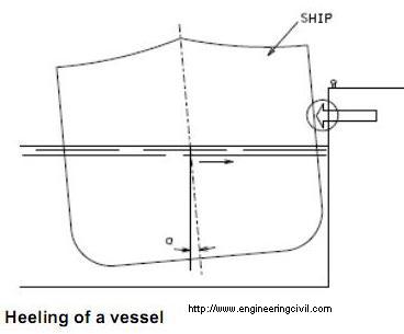
What is heeling during vessel berthing?
When a vessel berths on a fender system at a pier, the point of contact of the berthing ship may be above or below the centre of gravity of the ship. During the berthing operation, some kinetic energy is dissipated in work done to heel the ship i.e. the work done to bring the ship an angle of heel. This energy is normally a small fraction of total berthing energy and therefore it is normally not considered in design. However, designers should pay attention to the possible hitting of the berthing structure by the vessels in case the contact point is well above water level.
This question is taken from book named – A Self Learning Manual – Mastering Different Fields of Civil Engineering Works (VC-Q-A-Method) by Vincent T. H. CHU.
This question is taken from book named – A Self Learning Manual – Mastering Different Fields of Civil Engineering Works (VC-Q-A-Method) by Vincent T. H. CHU.
Why is sulphate-resisting cement not used in marine concrete?
The main components of Portland cement are tricalcium silicate, dicalcium silicate, tricalcium aluminate and tetracalcium aluminoferrite. In sulphate-resisting cement, it contains a low amount of tricalcium aluminate in order to avoid sulphate attack. Otherwise, tricalcium aluminate would react with sulphates to form calcium sulphoaluminate and gypsum that cause expansion and crack the concrete structure.
However, for marine concrete sulphate-resisting cement should not be used because tricalcium aluminate has high affinity for chloride ions. This is based on the possible reaction of chloride ions and tricalcium aluminate to form calcium chloroaluminate hydrate as suggested by P. Kumar Mehta (1991) and the reduction of which may increase the rate of chloride attack to the concrete marine structure and result in faster corrosion of steel reinforcement in marine structures.
This question is taken from book named – A Self Learning Manual – Mastering Different Fields of Civil Engineering Works (VC-Q-A-Method) by Vincent T. H. CHU.
Should dolphins be designed in a rigid manner, i.e. resting on several raking piles?
In designing dolphins, they are normally supported on a system of three to four raking piles. This in essence is a rigid structure and exhibits little flexibility e.g. movement against impact and berthing loads by vessels. In fact, this kind of design may not be desirable in terms of maintenance because the dolphins are readily susceptible to damage by high berthing vessels. To rectify this situation, some energy absorption devices like rubber/plastic fenders have to be installed to reduce the impact load deriving from its own deflection. On the other hand, by designing dolphins as flexible structures capable for allowing slight deflection, it helps to reduce the large forces generated during berthing of vessels. In this connection, one way of designing dolphins as flexible structures is by provision of a single pile only.
Note: For a rigid structure, it takes up external loads without undergoing excessive deformations.
Note: For a rigid structure, it takes up external loads without undergoing excessive deformations.
Shall a layer of wearing course or additional thickness be designed on the surface of piers?
In the design of piers, consideration should be given to the effect of wearing action caused by passengers, other traffics and even sometimes vehicles. In maritime environment, the durability and integrity of concrete is detrimental to the servicing life of piers because it acts an essential barrier to chloride attack. However, in view of these gradual wear and tear generated by the loading traffic, some forms of surface protection should be provided on top of pier surface like wearing course or additional increase in concrete cover.
This question is taken from book named – A Self Learning Manual – Mastering Different Fields of Civil Engineering Works (VC-Q-A-Method) by Vincent T. H. CHU.
This question is taken from book named – A Self Learning Manual – Mastering Different Fields of Civil Engineering Works (VC-Q-A-Method) by Vincent T. H. CHU.
Why are high and narrow beams not desirable in concrete piers?
Based on past experience in other countries (Carl A. Thoresen (1988)), high and narrow beams after several years of construction showed signs of serious deterioration at the bottom of the beams. However, the deterioration of pier slabs was not significant when compared with that of the deep beams. The main reason to account for this is due to the close proximity of the deep beams to the sea level. To avoid these problems, either beamless slab or wide with shallow beams are normally designed.
Why is shallow bedrock condition unfavorable for open berth piers?
The most severe load on piers generally is the horizontal load due to berthing of large vessels. Since the widths of open berth piers are relatively small so that they provides a short lever arm to counteract the moment induced by berthing loads. Moreover, the dead load of open berth piers are normally quite light and therefore the resisting moment provided by the dead load of pier structures may not be sufficient to counteract the moment generated by berthing loads.
To aid in providing adequate resistance to the overturning moment by the berthing load, the soil resistance above bedrock contributes to stabilizing moment. For commonly adopted marine piling type, i.e. driven steel tubular piles with reinforced concrete infill, driven piles can at most be founded on top of rockhead surface. In case the rockhead level is shallow, then the little soil cover may result in insufficient lateral resistance to the berthing load.
This question is taken from book named – A Self Learning Manual – Mastering Different Fields of Civil Engineering Works (VC-Q-A-Method) by Vincent T. H. CHU.
Why is it desirable to select fenders with low reaction force?
It is always in the interest of engineers to select fenders with high energy absorption with low reaction force. The reaction force is an important factor in the design of quay walls because sufficient savings could be resulted from low reaction force exerted by fenders. In many fender systems such as rubber fender, load-spreading panel is often adopted to cater for high reaction force. Hence, the use of fenders with low reaction force gets rid of the need of load-spreading panel so that significant economies could be made.
This question is taken from book named – A Closer Look at Prevailing Civil Engineering Practice – What, Why and How by Vincent T. H. CHU.
This question is taken from book named – A Closer Look at Prevailing Civil Engineering Practice – What, Why and How by Vincent T. H. CHU.
What is the difference between breasting dolphin and mooring dolphin?
A dolphin is an isolated marine structure for berthing and mooring of
vessels. It is not uncommon that the combination of dolphins with piers could drastically reduce the size of piers.
Dolphins are generally divided into two types, namely breasting dolphins and mooring dolphins. Breasting dolphins serves the following purposes:
(i) Assist in berthing of vessels by taking up some berthing loads.
(ii) Keep the vessel from pressing against the pier structure.
(iii) Serve as mooring points to restrict the longitudinal movement of the berthing vessel.
Mooring dolphins, as the name implies, are used for mooring only and for securing the vessels by using ropes. They are also commonly used near pier structures to control the transverse movement of berthing vessels.
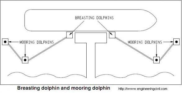
This question is taken from book named – A Closer Look at Prevailing Civil Engineering Practice – What, Why and How by Vincent T. H. CHU.
vessels. It is not uncommon that the combination of dolphins with piers could drastically reduce the size of piers.
Dolphins are generally divided into two types, namely breasting dolphins and mooring dolphins. Breasting dolphins serves the following purposes:
(i) Assist in berthing of vessels by taking up some berthing loads.
(ii) Keep the vessel from pressing against the pier structure.
(iii) Serve as mooring points to restrict the longitudinal movement of the berthing vessel.
Mooring dolphins, as the name implies, are used for mooring only and for securing the vessels by using ropes. They are also commonly used near pier structures to control the transverse movement of berthing vessels.
This question is taken from book named – A Closer Look at Prevailing Civil Engineering Practice – What, Why and How by Vincent T. H. CHU.
What is the difference in design philosophy between flexible dolphin and rigid dolphin?
(A) Rigid dolphin
The impact energy of vessel is absorbed mainly by fender. As such, the dolphin itself is designed as a rigid structure with a group of piles. The piles serve to transfer the reaction force from fender system to the foundation soils. The design of rigid fender is similar to other structures and the strength and stiffness of rigid dolphin should be sufficient to withstand berthing forces without causing excessive deformations.
(B) Flexible dolphin
The impact energy of vessel is absorbed by lateral deflection of piles. The dolphin itself performs both the functions of fender and berthing structure. Flexible dolphin is particular suitable in deep water region because the energy absorption capacity is a function of pile length. The pile stiffness could not be designed to be too low because large deflection of pile may occur so that the pile may touch the jetty or the vessel may touch the pile. On the other hand, pile stiffness could not be designed to be too high because of potential yielding of piles or vessel’s hull.
This question is taken from book named – A Closer Look at Prevailing Civil Engineering Practice – What, Why and How by Vincent T. H. CHU.
Which configuration is better, finger jetty or T-shaped jetty?
Finger jetty is a more efficient pier structure because it could accommodate vessels at both sides of the jetty. However, there should be sufficient water depth as the berths at finger jetty is relatively close to shoreline when compared with T-shaped jetty so that it is anticipated that vessels are required to berth at shallower water. Moreover, there should be no cross current to enhance berthing at both sides of finger jetty. Also, as mooring points are often located on the jetty, leads are not ideal for larger ships.
T-shaped jetty allows higher water depth for vessels to berth. Moreover, with the installation of breasting dolphins and mooring dolphins, it allows the berthing of larger vessels.
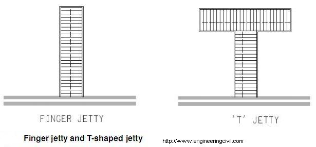
T-shaped jetty allows higher water depth for vessels to berth. Moreover, with the installation of breasting dolphins and mooring dolphins, it allows the berthing of larger vessels.
In mooring of vessels, wire ropes or fibre ropes are commonly used for tying the vessels to mooring system. It is not recommended to use them together in mooring. Why?
Mooring lines are provided by vessel while the shore provides the mooring points. Wire ropes provide a more rigid mooring system than fibre ropes. When a high degree elastically is required, fibre ropes would be a better choice. The mixed usage of wire ropes and fibre ropes is not recommended because of the uneven tensioning of ropes. Owing to different material properties associated with wire ropes and fibre ropes, it is almost impossible to allocate uniform tension on both types of wires. As a result, there is possible occurrence of overloading in some ropes.
This question is taken from book named – A Closer Look at Prevailing Civil Engineering Practice – What, Why and How by Vincent T. H. CHU.
This question is taken from book named – A Closer Look at Prevailing Civil Engineering Practice – What, Why and How by Vincent T. H. CHU.
It is a very informative and useful post thanks it is good material to read this post increases my knowledge. Marine Piling Sleeves & Piling repair
ReplyDelete